• Please review our updated Terms and Rules here

Home-made SD2IEC available

Koolstar42

Experienced Member
Joined
Sep 24, 2019
Messages
68
Location
Netherlands
Hi all,

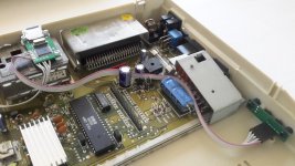
I built an SD2IEC with a PCB of my own design.
It is based on the Shadowolf schematics, using SMD parts and a micro-SD socket.
I can make some more for someone interested, at cost, ($5.00, including shipping - letter < 20 gram).
Please check the enclosed picture and note that it is intended to be fitted inside the CPU enclosure, and some soldering will be required, as well as the deft use of drills, knives and files.
Due to new customs regulations, shipping to the USA (including territories) has become a PITA. US customs now requires to be notified of arrival of any goods into the US prior to shipping. As I live in Europe, this means that shipping is now ridiculously expensive. (minimum cost EUR 23).
I can also post Gerbers and schematics of this project, so you can order your own boards.
sd2iec.jpg

Rienk
 

Attachments

  • sd2iec.jpg
    sd2iec.jpg
    162.9 KB · Views: 4
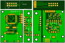
This design is a further evolution of the one shown previously. I realized that not everyone can flash an AVR prior to soldering it in, so I added a SD-to-ISP interface. Essentially an SD-card outline with an ISP connector attached. The SD card exposes MISO, MOSI, SCLK, VCC and GND. Reset is exposed on the unused pin 1 when R16 (PRG - 0ohm) is soldered in.
This PCB should be ordered 0.8 mm thick, so this programming card will fit. You will have to cut along the white lines to separate the three components, then file the SD-card to the correct shape.
R14 and R15 are zero ohm resistors for setting the device address. for device 8 they should be omitted.
MOSFETs are listed as 2n7002, but other ones can be used. I fitted A2SHB with no issues.
The SD-card connector is the cheapest self-ejecting type on EBay, I don't know brand and type. Look and you shall find.
I did not test this particular design, but it is generated from the same schematics as the ones used for the prototype (now with programming added), so I expect no issues. but hey, Caveat Utilitor, ymmv
I can also release the KiCad files, but it uses custom libraries. so I have to make a "package"

This is not intended to cut anyone's business, I just want to keep this hobby as affordable as possible.

Questions? let me know
Screenshot.png
 

Attachments

  • SD2IECv3.pdf
    90.7 KB · Views: 2
  • SD2IECv3.zip
    40.1 KB · Views: 2
Clever idea on the sd/isp interface! May have to borrow that for future projects.
Looks great, thanks for the information. I have a PCB order in progress right now, might try this out. Pretty sure I have some of that same micro sd socket, also got those on eBay.
Well done!
Did you need to make any modifications to the sd2iec firmware?
 
Also, just looking at the schematics, curious about the 8MHz crystal, since the ATmega644 already has an internal oscillator at that frequency. Is that required because the internal oscillator is not precise enough?
 
No, I did not modify the firmware. Had a cursory look at it, mainly to validate the hardware. It works well enough, so why mess with a working system. It uses firmware sd2iec-1.0.0atentdead0-24-ga9a09fa-sw2-m644p.bin, with bootloader newboot-0.4.1-sw2-m644p.hex and fuses lo = 0xef, hi = 0x91 and ext = 0xfd.
You could try running without the crystal, but it is only a 30 cent part, admittedly about 10% of the cost :). I don't know how tolerant the IEC interface is to frequency variation.
For completeness I include the KiCAD files. I routed this with freeroute.
I included a libraries section , containing the custom parts and footprints. You will probably have to be a bit creative in putting everything in its correct place in your filesystem.
 

Attachments

  • SD2IECv3.KiCad.zip
    120.2 KB · Views: 1
Back
Top