• Please review our updated Terms and Rules here

Amiga 500 Dual Internal Floppies

grbrady

Experienced Member
Joined
Oct 10, 2020
Messages
101
Location
Baltimore, MD
I had a spare A500 motherboard that I decided that I'd like to mount in a Checkmate A1500plus case (https://www.checkmate1500plus.com/.) Since it has multiple internal floppy drive bays I thought it would be nice to mount both a Gotek and the original 3.5" floppy drive as internal devices. Unfortunately the A500 internal floppy interface doesn't support this. Others have done this by plugging the second floppy drive into the external connector and the routing the cable back inside the case. This seems inelegant to me, so I decided to try to figure out what circuit is necessary to hook up a second internal floppy to the motherboard. I closely followed the circuit for this on the Amiga 2000 motherboard.

What I've come up with is a schematic for a board that you plug into the even CIA socket (U8.) You also plug in the internal floppy cable to this board. The board routes and generates the required signals and outputs them a second internal floppy connector. You attach a 34 pin ribbon cable with three connectors, with a twist between the two drive connectors, as in the A2000.

I was hoping some of the Amiga experts on here could take a look at the schematic to see if I've done anything clearly wrong. I'm somewhat inexperienced at this and am taking this as an opportunity to learn KiCAD and PCB layout in general.
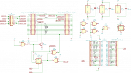
a500_dual_floppies_schematic.png - Click image for larger version  Name:	a500_dual_floppies_schematic.png Views:	0 Size:	159.6 KB ID:	1210804

Thanks,
Greg
 
Maybe a silly idea, but...

Using a normal flat cable (with or without the cross section, depending on your drives configuration) connected to the internal floppy connector, shouldn't allow you to connect two internal floppy drives, one seen as DS0 and the other as DS1?

I know almost nothing about Amiga, but afaik the floppy connector is the same of a PC connector, except for pin #34 (Ready) and #2 (Disk Change) [the PC use the D.C. at pin #34]. The pin #10 and #12 (Select Disk 0 and Select Disk 1, respectively) are the same.
 
It seems Amiga floppy drives are somewhat different from PC drives, although both are based off the Shugart standard. First off, there is no "motor on" signal routed to the internal connector for the second drive, so that has to be generated using the logic with the flip flop to turn on the transistor when the second internal drive is to turn on its motor. Second, all drives but the first internal drive must generate an "ident" bit string on the "_RDY" line. External drive enclosures for Amigas generate this sequence and Amiga motherboards designed for use with multiple internal drives do as well such as the Amiga 2000. The logic attached to the "_RDY" line is supposed to do this. I've lifted this circuit directly from the Amiga 2000 schematics.
 
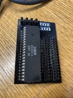
I got the boards back that I had made according to the schematic above and they seem to work perfectly in my cursory testing. Here's a photo of what the finished product looks like:
IMG_7369.jpg

I went with surface mount package logic chips and BJT instead of the good old DIP package ones I show in the schematic. This let me hide them under the CIA and make the board more compact. As I said, everything works well and the jumpers let me configure whether the Gotek or the original floppy drive is DF0:/DF1:. I'll probably connect a switch to that header at some point so I can change it without opening the case.

This was a fun little project and I'm pretty pleased that it worked out.
 
It seems Amiga floppy drives are somewhat different from PC drives, although both are based off the Shugart standard. First off, there is no "motor on" signal routed to the internal connector for the second drive
If it follows the Shugart standard, then there is no individual motor control for each drive. When you access one disk drive, the motors of all floppy drives attached to the interface turn on. I know TRS-80s and Tandy 1000s work this way.
 
If it follows the Shugart standard, then there is no individual motor control for each drive. When you access one disk drive, the motors of all floppy drives attached to the interface turn on. I know TRS-80s and Tandy 1000s work this way.

I may have explained that poorly, as I'm no expert on floppy interfaces. I think it might be more accurate to say that we need to generate a motor on signal for when the second internal floppy gets accessed since in the Amiga 500 that signal gets routed only to the external connector. The motor on signal on the internal connector doesn't normally get asserted when any drive but the (normally lone) internal drive gets accessed. Again, I don't have a complete (or even working) understanding of how the interface works. All I've done here is replicate the Amiga 2000 floppy port in an Amiga 500 so that two internal floppy drives can be supported.
 
Hi are you making the files available or perhaps selling the pcbs?
 
Back
Top