• Please review our updated Terms and Rules here

The McGyver guide for 6550 RAM socket fix

giobbi

Veteran Member
Joined
Dec 23, 2012
Messages
987
Location
São Paulo country, Brazil
Forget Lucifer, Commodore socket is evil :D


I had a lot of issues related with the Commodore sockets, especially (but not only) the PET sockets. Contact cleaner, alcohol etc. don't solve: sometimes the problem is mechanical: loosen clips that make bad or no contact at all. So, when I'm having some trouble and there's a socket involved, my first move is to replace the socket with a good one.
----
I have a chiclet PET with 6550 RAM, that has a slightly bigger pitch respect the normal ICs like 2114. I cannot find an appropriate socket with the right size. Maybe some on-line shop like Mouser etc. sells them, but the shipping fees to Brazil are absurdly expensive.

After analyzing the original socket, I decided for a McGyver DIY fix (of course I had a B plan, but luckily I didn't need it).


The 6550 socket, at least the ones I had, were made in two part glued together: I opened them with a blade.
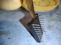
Click image for larger version  Name:	IMG_20210825_181813.jpg Views:	0 Size:	115.6 KB ID:	1222628

Then I removed the pins: I kept the shell and thrown the cover:
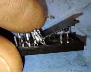
Click image for larger version  Name:	IMG_20210825_124434.jpg Views:	0 Size:	145.0 KB ID:	1222632

some precision sockets were the pin donors: it's just a matter to warm them, melting the plastic case, and push them out of the shell.
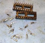
Click image for larger version  Name:	IMG_20210825_130630.jpg Views:	0 Size:	137.9 KB ID:	1222633

then I took and old, broken C=64 board as workbench and I put every pin into the 6550 shell, just pushing them through the hole.
Note: the lower part of the shell (the one that was turned to the PCB) now it's the upper part that will receive the IC.
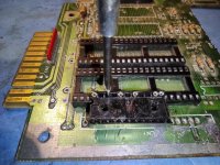
Click image for larger version  Name:	IMG_20210825_124434.jpg Views:	0 Size:	145.0 KB ID:	1222632

One row is done: time to do the other row.
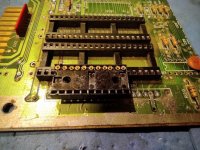
Click image for larger version  Name:	IMG_20210825_124434.jpg Views:	0 Size:	145.0 KB ID:	1222632

Click image for larger version  Name:	IMG_20210825_124434.jpg Views:	0 Size:	145.0 KB ID:	1222632
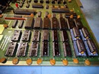
And finally all the sockets are succesfully soldered in the board. No more bad contact on my RAM ICs!


Note the 2114 -> 6550 adapter. I still have eighteen 6550 RAM chips working, but I'm going to preserve them, using the (expendable) 2114 RAM instead.

The 2114 -> 6550 adapter was made using the D'Asaro's schematics: a local pcb factory did them for me using the schematics with a little mod: I can now use a normal hair pin connector instead of the personalized pins of the original design. I just mounted 6 (the four in the picture + the two video RAM), I'm going to build all, but the smd chip is quite bad and bother to solder, so I'm doing a couple at a time ;-)


It took me about 6 hours to remove, rebuild and solder back the eighteen sockets (16 RAM + 2 video RAM). I did two at a time, testing them before to jump to the next two.
 

Attachments

  • IMG_20210825_181400.jpg
    IMG_20210825_181400.jpg
    140.4 KB · Views: 5
When you say "larger pitch" do you mean the width between the pin rows, or the spacing of the pins themselves? (IE, is it not the standard .1"?) I mean, I'm not going to criticize either way, but if it's row spacing you can get breakaway machine pin header strips pretty inexpensively. A pair of those clipped to the correct size and soldered in place should look about the same as a full socket as long as a chip is plugged in on top of it.
 
When you say "larger pitch" do you mean the width between the pin rows, or the spacing of the pins themselves? (IE, is it not the standard .1"?) I mean, I'm not going to criticize either way, but if it's row spacing you can get breakaway machine pin header strips pretty inexpensively. A pair of those clipped to the correct size and soldered in place should look about the same as a full socket as long as a chip is plugged in on top of it.

the IC width: the space between the rows.

your idea was the first I tried, of course, but that way the single rows tend to be quite fragile and easy to bend on one side or another, and the result didn't satisfy me. So I decided for the "MacGyver" way LOL
 
your idea was the first I tried, of course, but that way the single rows tend to be quite fragile and easy to bend on one side or another, and the result didn't satisfy me. So I decided for the "MacGyver" way LOL

Yeah, I guess I could buy that. At the very least you'd probably want to have something inserted to hold them straight at the desired end-spacing while you're soldering them in. I've found that issue kind of a nightmare generally when soldering headers if it matters if they're standing straight up. (Last few times I've soldered boards with pin headers I built jigs out of the matching header and lego pieces to support it.)
 
You do know that you can purchase inexpensive single-row machine-pin socket strips from China, don't you?

These for example. I've been using these for 0.1" pitch IC sockets for years now. I don't have to worry about row spacing.
 
You do know that you can purchase inexpensive single-row machine-pin socket strips from China, don't you?

These for example. I've been using these for 0.1" pitch IC sockets for years now. I don't have to worry about row spacing.

Beat you to it... although the eBay link is a buck cheaper than the Amazon link I dropped in, even if you have free Prime shipping. ;)
 
Indeed you did! As I said, however, I almost never use regular sockets anymore, unless I've already got a bunch aching to escape the confines of a parts bin.
 
I know this is an awful thing to say, but I kind of prefer crap wiper sockets to machine pin for my homemade projects where the only reason I'm using sockets is because I don't trust myself not to make a stupid mistake and solder an IC in backwards. I apparently have magical butterfingers which prevent me from getting IC pins lined up correctly enough to smoothly insert into that tiny little machine pin hole.
 
One thing to keep in mind is what happens to the IC socket claw mechanism, when anything other than a standard IC pin is inserted into it.

The thickness of IC pins, across the flat is only about 0.26mm and typically less than 0.5mm across the wide part, usually around 0.45mm. Most machine pin IC sockets have pins that are about 0.5mm diameter, or just a little over that, also, unless you hunt around, most of the machine pin header strips are like this too. If these are inserted into machine pin IC sockets, they ruin them for insertion of an IC later, they also reduce the tension on the claws of dual wipe sockets as well, and weaken the spring contact force significantly, making them unreliable if a real IC pin is inserted into them later. This was figured out by the good people at Winslow Adaptics, and many of their IC adapter boards have pin diameters that are less than 0.5mm, around 0.43mm, even that small amount helps, so they don't stretch IC socket claws that may later receive a IC pin directly. Of course if you never plan to put an IC directly back in the socket, it might be academic.

One thing you might see is when some people, who either store, or ship machined pin IC sockets, to keep them all together, insert them into each other. When I have received these like this, I throw them in the bin because I know what it means for the socket reliability. Sometimes if this is done they will barely even hold onto an IC as the forces per pin are grossly diminished.

I could also mention that if you want to get the machine pins out of a donor socket, without heating, for some other use (for example you can make transistor sockets out of them), the plastic material is fairly brittle, so if you cut with miniature sharp nosed side cutters, near the pin, the plastic splits away releasing the pins.
 
Last edited:
Early IC sockets were pretty terrible. I had nightmares with the low-profile TI sockets. Then I discovered the Augat machine-pin sockets. My life changed at that moment. :)
 
Early IC sockets were pretty terrible. I had nightmares with the low-profile TI sockets. Then I discovered the Augat machine-pin sockets. My life changed at that moment. :)

The TI sockets were a little unusual in that the claw mechanism grips the IC pin from side to side, unlike practically every other dual wipe socket that does it across the thinner pin dimension. It is a very small surface area of contact. My SOL-20 was full of these TI sockets and the sides of all the IC pins had a line of corrosion where the dissimilar metals were in contact. It was a big job to clean up all those IC pins & sockets. I didn't want to replace all the sockets due to that stressing the pcb, so I patiently cleaned them all up and repaired the ones that had lost their spring tension. At least with the TI sockets it is possible to lift the plastic shrouds off them to access individual defective socket claws for repair or replacement.
 
You do know that you can purchase inexpensive single-row machine-pin socket strips from China, don't you?

These for example. I've been using these for 0.1" pitch IC sockets for years now. I don't have to worry about row spacing.

yeah Im with Chuck. I keep these on hand just for situations like this. Seems like alot of work when a solution was cheaply available.

Glad you got it fixed though.
 
As for removing machine pins, I use a block of wood with a hole drilled, a little larger than the machine pin. I place the socket upside down over the hole and push the pin from the bottom with short needle pliers. It doesn't take much force and the pop out. That is how I make adapter sockets, where I don't want the feed through connection. They are usually made with three layers of machine pin sockets, depending on what needs to be connected. I can the cross wire or tack in a surface mount IC for needed logic.
Dwight
 
I've machined a tool for a similar purpose (pushing socket pins out from wirewrap prototype boards). Basically a brass rod with a wooden handle; said rod having a small hole drilled in the center. and the last inch or so of the rod turned down to fit between the pins. The force is always straight downwards, with no bent or damaged pins.
 
I'm lucky enough that all sockets on my 2001 are still making good contacts, but whenever I needed to change a socket for a 6550 SRAM, I've just opted for a ready-made 400 mils
22 pin socket like digikey's PN 1212-1016-ND.
HTH
Frank IZ8DWF
 
I've found that issue kind of a nightmare generally when soldering headers if it matters if they're standing straight up. (Last few times I've soldered boards with pin headers I built jigs out of the matching header and lego pieces to support it.)

A good trick, for a poor solderer like me that "bitfixer" taught me, is to solder only the end pin first. Then you can take your time while you reflow that joint making sure the row is square to the board before soldering the other pins.
 
Back
Top