• Please review our updated Terms and Rules here

Suitable EPROM replacement for DOS ROMs in 2040 disk drive?

Eudimorphodon

Veteran Member
Joined
May 9, 2011
Messages
7,005
Location
Upper Triassic
Trying to be optimistic about my prospects for getting a PET working someday...

I've been looking at the disk drives I picked up from the Albany Computer Services warehouse dump. I have two of the big dual-chassis drives, an 8050 and a 2040 that has a sticker on it that says "Updated to 2.0" (And then the 2.0 is scratched out and "2.1" is written underneath it.) The 8050 appears to pass diagnostics. (I won't know any more than that until I can get a working machine to drive it with.) The 2040, however, goes into a loop where it blinks all its LEDs three times, pauses, repeats.

According to the Commodore 8050 service manual (I can't seem to find a 2040/4040 specific flash decoder) three blinks means a bad DOS ROM. So, two questions:

1: Since I can't seem to find the 2040 blink codes, does anyone know which ROM three blinks translates to? (The 8050 appears to use 8k ROMs while the 2040 is 4k.) I'd love to not have to burn replacements for all three because of question #2.

2: Is there an EPROM that's a close-to-drop-in replacement for the ROMs in the 2040? I did find this thread:

http://www.vintage-computer.com/vcf...pairing-a-Commodore-2040-IEEE-488-drive/page3

And if I'm interpreting it at all correctly unlike a PET's 4k ROMs I can't simply drop in a 2532 because pin 21 is a TTL chip select line instead of being tied to 5+ volts? There's also mention of a speed-related issue. (I believe the 2532s I have access to are 450ns.) My *guess* is that my best bet is to make adapters for 2732s like these:

http://personalpages.tds.net/~rcarlsen/tdsweb/EPROM/2732sub.gif

But I'm wondering if anyone has better ideas. (Of course, with my luck it's not going to be a bad ROM at all...)

Thanks.
 
According to a somewhat random assemblage of notes on IEEE drives I found online somewhere, 3 flashes on a 2040 or 4040 means the ROM at position L1 on the board, which should have one of the numbers 901468-06, 901468-12, or 901468-15.
 
Last edited:
According to a somewhat random assemblage of notes on IEEE drives I found online somewhere, 3 flashes on a 2040 or 4040 means the ROM at position L1 on the board, which should have one of the numbers 901468-06, 901468-12, or 901468-15.

Thanks. I'll try burning the EPROM for that position and making an adapter out of a set of sockets.

(This particular drive has the what appears to be the "latest" DOS ROMs, the 901468-14, 901468-15, 901468-16 "Revised" set, which must be why someone wrote "upgraded to DOS 2.1" on it. The parts list on Zimmers shows two possible part numbers for the RIOT chip in UK3, a "DOS 1" and a "DOS 2" version. This drive has the 901466-04 "DOS 2" part, which hopefully is correct one.)
 
(This particular drive has the what appears to be the "latest" DOS ROMs, the 901468-14, 901468-15, 901468-16 "Revised" set, which must be why someone wrote "upgraded to DOS 2.1" on it. The parts list on Zimmers shows two possible part numbers for the RIOT chip in UK3, a "DOS 1" and a "DOS 2" version. This drive has the 901466-04 "DOS 2" part, which hopefully is correct one.)


This set of firmware turns your 2040 drive into a 4040 drive that is compatible with the latest versions of PET BASIC and is 'read compatible' with the C64 1541 drive which is nice as they are readily available and are fairly easy to interface with a PC.

Also the 2040 did not automatically perform an 'Initialize' before every disk access to update the BAM. So when users slipped in a new diskette and saved a file without remembering to initialize the drive, the diskette could become corrupted.
 
Is there an EPROM that's a close-to-drop-in replacement for the ROMs in the 2040?

Ah, there is a long story there. The 2532 should have been compatible, but some sloppy design by Commodore prevented it.

Now the best way to would be to make an adapter to convert into the pinouts of a 2732 fit the pin outs of a 2332. In theory a 450 nS EPROM should barely work, but I would use a 250 nS version for reasons explained below.

Note that this 2332 has a positive chip enable at pin 21, and the signal going there is Phase 2 clock (1 MHz). This is done because the data bus is shared with another CPU during the opposite phase of the clock. That means since pin 18 of the 2732 is /CE, that a jumper will be needed from /Phase2 (Phase 2 NOT) on the 2040 board to pin 18 of the 2732, and that pin 21 of the original 2332 socket should not connect to the adapter. The other normal jumpers to make a 2732 interface with a 2332 would be needed.

If this was too confusing, I can gin up a sketch.
-Dave
 
Last edited:
If this was too confusing, I can gin up a sketch.

A sketch would be good, if it's not too much of a hassle. (Including a suggestion as to the best place to tap the phase 2 signal, if not from the ROM socket?)

I did already buy a 2732 to use as a replacement EDIT ROM should one of my dead PETs have needed it, suppose I should make sure it's fast enough.

Many thanks.
 
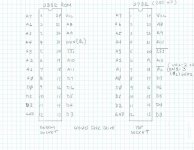
...I hope someone checks this diagram before a board is modified. MikeS where are you?
View attachment 6023
Away for the weekend ;-)

Looks good to me; as a matter of fact I just got involved in the positive-true CS issue with Jim Brain, albeit in an 8050; a customer was trying unsuccessfully to use one of his 2364<>2764 adapters to replace one of the 8050 ROMs, and Jim was asking what the problem could be.

The only issue might be timing; it looks like UA1 is only there to delay clock phase 2, so UA1-2 would be a little earlier. If I get a chance I could open up my 4040 and try replacing one of the ROMS with a 2732.
 
For pin 18 of the 2732, I called out a jumper to 'Phase 1' from the 6502 because my board does not match the board on Zimmers and I have no UA1. If you have a UA1, you can substitute UA1-2 rather than pin 37 of the 6502 chip.

Fun. I'm wondering if it might be worth investing in one of those little micro clips so I can try pinning a jumper wire to various places before deciding whether to solder it down. When I get a chance I'll take a look at my board and see how closely it does or doesn't match the Zimmer documentation.

I *really* need to get a PET working so I can dig into these drives properly. In addition to these Commodore drives I snagged an MSD SD-1 and it also passed the "smoke test"... and on top of that it appears to use a drive mechanism that I probably have a workable spare lying around for. (Months ago I saw a mint-looking 5 1/4 floppy drive in a recycle bin and thought it might come in handy someday. It appears to be almost the same model as the MDS' stock mechanism, just double-sided. That of course has me vaguely wondering if it's possible to hack an MSD SD-1 motherboard into an ad-hoc MSD SD-2...)
 
Fun. I'm wondering if it might be worth investing in one of those little micro clips so I can try pinning a jumper wire to various places before deciding whether to solder it down. When I get a chance I'll take a look at my board and see how closely it does or doesn't match the Zimmer documentation.

I hope your board matches the Zimmer documentation as UA1 pin 2 may be the best place. I had the wrong pin on the 6502 as it turns out. Pin 37 is Phase Zero input and is the WRONG signal. I wanted Phase 1 (pin 3) which is the inverse of Phase 2. I will edit the sketch.

To be closest to the original circuit, NOT_Phase 2 may be best (UA1-2).
 
A sketch would be good,

For pin 18 of the 2732, I called out a jumper to 'Phase 1' from the 6502 because my board does not match the board on Zimmers and I have no UA1. If you have a UA1, you can substitute UA1-2 rather than pin 3 of the 6502 chip. Here is the zimmer's schematic I am looking at:

http://www.zimmers.net/anonftp/pub/c...0/320806-1.gif

It seems to me that all pins are one to one except that pin 21 (A11) of the 2732 goes to pin 18 (A11) of the 2332, and pin 21 of the 2332 is not connected to the top adapter, and finally 2732 pin 18 goes to either UA1-2 or UN1-3.

I hope someone checks this diagram before a board is modified. MikeS where are you?

4040EPROM.jpg
 
The only issue might be timing; it looks like UA1 is only there to delay clock phase 2, so UA1-2 would be a little earlier. If I get a chance I could open up my 4040 and try replacing one of the ROMS with a 2732.

You didn't by any chance try this out yet, did you?

Thanks to being sick and otherwise distracted I sort of dropped the "fix the PET stuff" project on the floor for a while, but I was going to see about getting a 2732 burned. I guess I still need to see about comparing my 2040's motherboard to the Zimmer's schematics and see if I can find the landmarks that have been mentioned...
 
Back
Top