• Please review our updated Terms and Rules here

Rev E KIM-1 - appears dead

snuci

Veteran Member
Joined
Nov 22, 2012
Messages
1,557
Location
Richmond Hill, Ontario, Canada
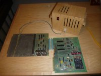
Just picked up a Rev E KIM-1 but it appears dead. I don't see any flicker of life when I turn on the power supply. I know the power supply is good because it powers up my Rev F with no problem. On this board, the cylindrical yellow capacitors seem "squished". It's like they have been slightly flattened. Oddly enough, one of my Rev F yellow cylindrical capacitors seems flattened also. Is this normal?

Here's a pic:

DSCN0029.jpg

Has anyone created any sort of troubleshooting guide? I'll go through the schematic (I have the big poster) and check voltages tomorrow but I don't want to play with it too much in case I do more harm than good.

Any help or tips are always appreciated.
 
Hey Snuci, Does that board have any "tantalum" capacitors? If so check for shorts on the power bus. Also might try those bigger yellow ones as well. Sounds like a Power buss short somewhere. But just a guess. Good luck
 
The first thing is to check out the power rails. As Frank has said - a short-circuit decoupling or smoothing capacitor won't do your KIM-1 any harm - but neither will it do your working power supply any good!

Check across the VCC and GND pins of a few chips for between +4.9V and +5.1V. TTL chips will work outside of this range (from 4.75V to 5.25V) but I would tighten the range for older computers.

I would measure the power supply current to make sure that it is not excessive. If I remember correctly, the recommended PSU was +5V at 1A - so anything above 1A would be considered suspect. +12V at 50 mA was also required for the audio interface if I remember correctly. In fact, I would consider 1A for an unexpanded KIM-1 to be high...

If things check out OK there - it is unlikely that leaving the power on will cause problems.

Next, I would check for a healthy RESET signal. U1 (6502) pin 40 should go LOW when the reset button is pressed and high when it is released.

Next I would be checking for a 1 MHz clock signal at U1 pin 3 and U1 pin 39.

Whilst looking at the schematics and the handbook I did come across one issue that may or may not apply to you. In an unexpanded KIM-1 there was a link required from DECEN (pin K of connector P2) to GND to enable the KIM-1 board. In an expanded KIM-1 this signal was driven externally. Is this link made or not in your case?

Have a look and see what you come up with from these steps and I will checkout how to test further.

Dave

PS: I can't see the capacitors too well in your picture - but I wouldn't worry about them too much at this stage. Some capacitors do look a little 'squashed' to save space.
 
The "squished" cap is normal. Different manufacturer most likely. Power problems can be a pain to fix. Have to find out what is pulling it down!
But hopefully something simple!
 
The first thing is to check out the power rails. As Frank has said - a short-circuit decoupling or smoothing capacitor won't do your KIM-1 any harm - but neither will it do your working power supply any good!

I simply checked the axial caps (no tantalums) with an ohm meter while there was no power. I checked across both leads. Would that tell me if there is a short? I also checked voltage in a few places. I didn't check 12 volts but it's probably there also with my power supply even if unneeded (more on my power supply below).

Check across the VCC and GND pins of a few chips for between +4.9V and +5.1V. TTL chips will work outside of this range (from 4.75V to 5.25V) but I would tighten the range for older computers.

My power supply puts out 4.89V. I checked all of the memory chips. It's hard to explain but I'm using a KIMSI board that connects to the expansion connector and two lines are going to the APP connector. Here's a picture to better explain (that's the Rev F KIM-1 that came with it):

kim-1-full-setup.JPG

I would measure the power supply current to make sure that it is not excessive. If I remember correctly, the recommended PSU was +5V at 1A - so anything above 1A would be considered suspect. +12V at 50 mA was also required for the audio interface if I remember correctly. In fact, I would consider 1A for an unexpanded KIM-1 to be high...

My power supply is 2A. Works great with my other two KIM-1s.


If things check out OK there - it is unlikely that leaving the power on will cause problems.

Next, I would check for a healthy RESET signal. U1 (6502) pin 40 should go LOW when the reset button is pressed and high when it is released.

Check.

Next I would be checking for a 1 MHz clock signal at U1 pin 3 and U1 pin 39.

I don't know how to use my scope too well yet but I see a sine wave.

Whilst looking at the schematics and the handbook I did come across one issue that may or may not apply to you. In an unexpanded KIM-1 there was a link required from DECEN (pin K of connector P2) to GND to enable the KIM-1 board. In an expanded KIM-1 this signal was driven externally. Is this link made or not in your case?

With the pic above, I believe it is.

Have a look and see what you come up with from these steps and I will checkout how to test further.

Thanks guys. I really appreciate it. The blue board is a beauty. Given the above, it seems that there's life in it. I hope it's not one of the RIOTs. Is it helpful that the reset button works?
 
Yes the reset might working would be a good thing. Check pin 40 of the 6502 and connect a meter to ground and pin 40. The reset should make that pin go from a low or near zero to high near 5 volts when pressed and released. Normal state of that pin is 5 volts or near that with reference to ground.
 
Yes the reset might working would be a good thing. Check pin 40 of the 6502 and connect a meter to ground and pin 40. The reset should make that pin go from a low or near zero to high near 5 volts when pressed and released. Normal state of that pin is 5 volts or near that with reference to ground.

Sorry if I wasn't clear above. I checked the reset on pin 40 with the reset button. When I press the reset button, it goes low. Otherwise, it is high (5v). I checked it with a meter.
 
Hi,

So far so good.

Yep, checking for a short across the power supply lines with an Ohmmeter is a pretty good way to start out. I don't think that I explained too well about the current consumption though. Your 2A power supply can supply a maximum of 2A at 5V under normal circumstances. Your unexpanded KIM should draw nothing like that current under normal circumstances! An excessively high current drawn from the power supply (especially with none of the LED displays lit) could indicate faulty components (e.g. leaky capacitors that may not have been detected by your Ohmmeter test and/or faulty semiconductor devices). Since you have another KIM as a reference, I would suggest measuring the current drawn from the 5V supply with your working KIM and then measure the current drawn from the 5V supply with your faulty KIM. The faulty KIM should draw less current than your healthy KIM (as the displays are not working). If the faulty KIM draws a larger current than your working KIM then this is not normal and the reason for it determined before continuing. In this case I would be tempted to keep the powered up times to a minimum.

It's great that you seem to have a working reset circuit and clock to start off with - and good news to hear that you have an oscilloscope!

I would proceed by following the clock circuit now we have seen something on U1 pins 3 and 39. Check U16 (7404) pins 13, 12, 11 and 10. They all should have a clock on them as well.

Next I would look at the 6502 address bus (especially A0 and A1). Do you see any logic changes here or not? If not - this probably indicates that the 6502 is not processing any instructions. It may be faulty, it may not be faulty. It depends on other signals being fed to the 6502.

Next I would look at U4 (74145). The 'D' input should be permanently '0' (this is our DECEN link that we identified before). You should see some activity on the A, B and/or C inputs. These are tied to some of the higher address lines of the 6502 CPU. If you see nothing on the address lines it is back to the CPU again. Continue to look at the K0, K5, K6 and K7 outputs from U4. These signals should normally be high but should 'flick' low briefly as the 6502 addresses the ROM, RAM and I/O. K0 addresses the on-board RAM. K5 addresses the I/O and K6/K7 address the ROM. You should see activity on K5. I would think there is a high probability of seeing activity on K0 and you should see activity on either K6 or K7 or both depending upon what part of the ROM is executing. You could (of course) compare what you are seeing on your faulty unit with your good one...

If this checks out OK - I would then look at the display section. I assume from the photograph that U2 is not in a socket and is soldered into the PCB? If so - proceed as follows (but ONLY if you understand what I am saying):

1) Connect a resistor of 1KOhm between the base of transistor Q1 and ground. This should enable transistor Q1 and the emitter of Q1 (connected to the first LED display - U18) should go to 5V.

2) Connect U17A (7406) pin 2 to ground.

Incidentally, the schematic I am using can be found here http://www.zimmers.net/anonftp/pub/cbm/schematics/kim-1/kim.gif

Segment 'A" of display U18 should illuminate.

Remove the link from U17A pin 2. The segment should be extinguished.

Repeat by linking each of the six outputs in turn from U17 to ground (plus the output from U26A pin 3). Each of the other segments in turn should light up.

WARNING: Resistors R26 to R32 are there to limit the current flow through the segment of the display device. Grounding the wrong side of the resistor will cause an excessive current through the display and would destroy it.

Move the link from the base of Q1 to the base of Q2 and so forth to test all of the other displays in turn.

This should prove whether the displays (and the transistors that drive them) are working.

I would like someone to check what I have said above before you perform this procedure just in case I have made some errors somewhere... The last thing I want to do is to tell you to do something that will further damage your new pride and joy!

That's probably enough for now...

Dave
 
Hi Daver2.

First off, thank you for the detailed instructions. This is great and I hope others who find this thread later will benefit from it also.

I did some initial checks from what you outlines but stopped because I don't think I'm using the scope correctly. More in a minute.

My second KIM-1 also draws (or is fed) the same 2A of power. I'm simply measuring from pad 23 and 24 on the top edge connector. The working KIM-1 works and the other one I am diagnosing does not. Incidentally, if I do not connecting the lower card edge connector in addition to the top connector from the power supply, the working one does not function so the lower connector is required.

I stopped when checking some of the scope measurements. i seem to be getting sine waves when I check some of the points you suggested. I am a oscilloscope newbie so I'm not sure how to check the points exactly. Should I not be seeing square waves (digital) for most of the points? This is where my confusion lies at the moment. Do I have to ground the probe when doing the checks? I apologize for the simple question but I am trying to learn. I fiddle with the time scale to a very short time to get a sine wave but I think I should be seeing a square wave, no?

If anyone can chime in, I would appreciate it. I've looked at various tutorials and I think I know how to operate it but what I think I should be seeing, I am not. In anticipation of an upcoming question, I have a Tektronics 465B, if it matters.

Thanks again for the help.
 
No problem - that's the best way to ask questions when unsure.

You seem to be confused by the terms Voltage, Current and Power so let me try and explain.

Voltage is measured in Volts. Batteries come in different voltages (e.g. 1.5V, 9V, 12V etc.). Your KIM-1 will only operate from 5V. The Voltage is a "potential to do work". Voltage is measured by a multimeter (or an oscilloscope) by measuring the voltage "across" something (i.e. on your KIM-1 it will be the potential difference between the ground and +5V line).

If there is nothing to make a circuit from the positive power lead to the negative power lead - then there is no current flow. Current is measured in Amperes and flows "through" a circuit. No circuit = no current = 0 Amps. So, to measure the current drawn by your KIM-1 you disconnect the +5V lead from the KIM-1 to the power supply unit and you connect your multimeter (set to read current) from the positive terminal of the power supply unit (which you have just disconnected) to the lead you have disconnected from the power supply unit that goes to the KIM-1. You are now going to measure the current drawn by (or flowing in) the circuit from the power supply unit (the source of the voltage) through the KIM-1 and back to the power supply unit.

The power is simply the product of the voltage (5V) times the current flowing in the circuit. This is ultimately dissipated in the form of heat.

If the KIM-1 has (say) a partially shorted component it will draw a much higher current than normal - hence the reading on the ammeter will go up.

If the KIM-1 is not doing much - then the current drawn will be much lower than 'normal'. If you measure the current flow of your working KIM-1 - then the current flow with your faulty unit should not be any higher than your working one (it stands to reason...) unless there is a fault somewhere...

You may need to checkout a couple of websites on the basics of voltage, current, resistance and power (it will be beneficial for you anyhow).

Your power supply will be able to provide (or supply) up to 2A. Any more than this drawn by the load (your KIM-1) will cause your power supply to start complaining - and will eventually 'trip out' on over current (if it has a trip) or fail by emitting the black smoke of death if it does't have a trip.

Yes, your oscilloscope should have a clip of some sort that should be permanently tied to the 0V (or ground) connection of your power supply unit feeding your KIM-1.

Dave
 
And yes, almost all of the signals on the KIM-1 should have 'square' edges.

The exception would be the clock around the crystal itself which may have some non-square signals.

If you do not have the 'scope grounded this would account for the sine wave (which will probably be a 50/60 Hz mains signal anyhow) so I would suggest re-testing the clock...

Dave
 
Back
Top