Upcoming Events:
- VCF South West - June 14 - 16, Davidson-Gundy Alumni Center at University of Texas at Dallas
- VCF West - Aug 2 - 3, Computer History Museum, Mountain View, CA
- VCF Midwest - Sept 7 - 8 2024, Schaumburg, IL
- VCF SoCal - Mid February 2025, Location TBD, Southern CA
- VCF East - April 2025, Infoage Museum, Wall NJ
-
Please review our updated Terms and Rules here
You are using an out of date browser. It may not display this or other websites correctly.
You should upgrade or use an alternative browser.
You should upgrade or use an alternative browser.
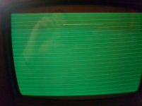
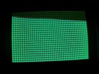
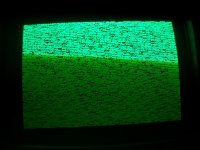
Commodore pet 3032 screen full of lines
- Thread starter Desperado
- Start date
daver2
10k Member
Of course we can  !
!
You appear to have horizontal and vertical synchronisation signals (i.e. A full screen raster), but no video signal.
The brightness looks as though it is turned right up possibly (or this may be a failure mode of the fault).
The first thing (as usual) is to check if you have any video signal at the connector on the PET main board that connects to the monitor. I can't remember if you have an oscilloscope or not? That would be the best piece of test equipment to use for this.
No video signal would indicate a fault on the main logic board. The presence of the video signal would indicate a fault on the monitor.
Divide and conquer!
Dave
Desperado
Veteran Member
- Joined
- Nov 25, 2017
- Messages
- 6,827
Of course we can!
You appear to have horizontal and vertical synchronisation signals (i.e. A full screen raster), but no video signal.
The brightness looks as though it is turned right up possibly (or this may be a failure mode of the fault).
The first thing (as usual) is to check if you have any video signal at the connector on the PET main board that connects to the monitor. I can't remember if you have an oscilloscope or not? That would be the best piece of test equipment to use for this.
No video signal would indicate a fault on the main logic board. The presence of the video signal would indicate a fault on the monitor.
Divide and conquer!
Dave
Hello Daver2 how are you??
Thanks for your answer!
Unfortunately i don't have scope but i ve a logic probe and multimeter!
Yes i ve seen that raster's trimmer was to max.....now i see only black screen...
daver2
10k Member
Fine thanks, just extremely busy at work...
Can you measure the dc voltage on J7 pin 1 relative to 0V/GND with your multimeter please. It should be somewhere between 0V and 5V and post the result.
Dave
Can you measure the dc voltage on J7 pin 1 relative to 0V/GND with your multimeter please. It should be somewhere between 0V and 5V and post the result.
Dave
Desperado
Veteran Member
- Joined
- Nov 25, 2017
- Messages
- 6,827
fine thanks, just extremely busy at work...
Can you measure the dc voltage on j7 pin 1 relative to 0v/gnd with your multimeter please. It should be somewhere between 0v and 5v and post the result.
Dave
j7 pin 1=4,8 v
daver2
10k Member
A voltage reading of 4.8 Volts seems too high to me. The implication being that the video output from the logic board is permanently high.
Can you detect any pulses (with your logic probe) on J7 pin 1 as a further cross-check?
The worrying thing is that a video signal level being high should be full white on the monitor (or green for a green screen monitor)...
I don't think you have two simultaneous faults, but it is possible...
Let me have a think for other tests that you can easily perform. dave_m might join in as well...
Dave
Desperado
Veteran Member
- Joined
- Nov 25, 2017
- Messages
- 6,827
A voltage reading of 4.8 Volts seems too high to me. The implication being that the video output from the logic board is permanently high.
Can you detect any pulses (with your logic probe) on J7 pin 1 as a further cross-check?
The worrying thing is that a video signal level being high should be full white on the monitor (or green for a green screen monitor)...
I don't think you have two simultaneous faults, but it is possible...
Let me have a think for other tests that you can easily perform. dave_m might join in as well...
Dave
With logic probe in pin 1 J7 i have always high signal....
daver2
10k Member
Definitely no video from the main logic board then.
Not sure (with the signal level being high) why you haven't got a white/green raster...
Dave
Not sure (with the signal level being high) why you haven't got a white/green raster...
Dave
Desperado
Veteran Member
- Joined
- Nov 25, 2017
- Messages
- 6,827
Definitely no video from the main logic board then.
Not sure (with the signal level being high) why you haven't got a white/green raster...
Dave
[SUP][/SUP]
Today i try to read all roms with eprom programmer, so i can compare with the original files....
Basic 2??
Thanks
dave_m
Veteran Member
Today i try to read all roms with eprom programmer, so i can compare with the original files....
Not needed yet.
You need to see why no video data. See p.8 of schematic http://www.zimmers.net/anonftp/pub/cbm/schematics/computers/pet/2001N/320349-8.gif
Check why G11-pin 6 is stuck high. Check inputs with logic probe: pin 1,2, 4, and 5 of G11 7420 4-input NAND gate. One of those may be stuck low.
Desperado
Veteran Member
- Joined
- Nov 25, 2017
- Messages
- 6,827
Not needed yet.
You need to see why no video data. See p.8 of schematic http://www.zimmers.net/anonftp/pub/cbm/schematics/computers/pet/2001N/320349-8.gif
Check why G11-pin 6 is stuck high. Check inputs with logic probe: pin 1,2, 4, and 5 of G11 7420 4-input NAND gate. One of those may be stuck low.
Ok thanks!
G11:
Pin 1=high
Pin 2=pulse
Pin 4=low
Pin 5=pulse
daver2
10k Member
OK thanks.
So G11 pin 4 is bad.
Can you check the following pins for pulsing with your logic probe please:
G10 pin 6 (74LS00).
G10 pin 8 (74LS00).
G9 pins 8 and 9 (74LS74).
E11 pins 7 and 9 (74LS165).
Basically, I am working backwards on the schematic diagram until we find where things go from GOOD to BAD...
Dave
Desperado
Veteran Member
- Joined
- Nov 25, 2017
- Messages
- 6,827
OK thanks.
So G11 pin 4 is bad.
Can you check the following pins for pulsing with your logic probe please:
G10 pin 6 (74LS00).
G10 pin 8 (74LS00).
G9 pins 8 and 9 (74LS74).
E11 pins 7 and 9 (74LS165).
Basically, I am working backwards on the schematic diagram until we find where things go from GOOD to BAD...
Dave
Hello,
this evening i tried to verify all roms with my eprom programmer and unfortunately, i verified correct only the char rom and edit rom
The others 3 roms are bad
daver2
10k Member
It doesn't matter - you don't have a CRT controller chip on your board (the VDU logic is hardware) so you should still see the 'garbage' screen on start-up.
Concentrate on that for now and see if we can get a picture...
Dave
Concentrate on that for now and see if we can get a picture...
Dave
Dwight Elvey
Veteran Member
Fix one thing at a time, follow what Dave is asking for. You are getting great help. As for the ROMs, they may be different versions or it may be how you are reading them.
Dwight
Dwight
dave_m
Veteran Member
OK thanks.
So G11 pin 4 is bad.
Can you check the following pins for pulsing with your logic probe please:
G10 pin 6 (74LS00).
G10 pin 8 (74LS00).
G9 pins 8 and 9 (74LS74).
E11 pins 7 and 9 (74LS165).
Basically, I am working backwards on the schematic diagram until we find where things go from GOOD to BAD...
Dave
Right daver2! This may be a quick fix. It should be one of those signals.
Dwight Elvey
Veteran Member
The area that Dave is looking at is a to create inverted video. It could be stuck in one position.
My bet is with the E11 side of things but without data back, that is just a unfounded guess.
Dwight
My bet is with the E11 side of things but without data back, that is just a unfounded guess.
Dwight
dave_m
Veteran Member
My bet is with the E11 side of things but without data back, that is just a unfounded guess.
There aren't too many chips it can be: the E11 Shift Register, the G9 Flip Flop, or the G10 and H10 NAND gates. E11 is the most complicated part so your guess may be correct. Five minutes with a scope and we would have this thing fixed (as far as a video signal). Our Paninero will find it.
Desperado
Veteran Member
- Joined
- Nov 25, 2017
- Messages
- 6,827
OK thanks.
So G11 pin 4 is bad.
Can you check the following pins for pulsing with your logic probe please:
G10 pin 6 (74LS00).
G10 pin 8 (74LS00).
G9 pins 8 and 9 (74LS74).
E11 pins 7 and 9 (74LS165).
Basically, I am working backwards on the schematic diagram until we find where things go from GOOD to BAD...
Dave
For this test
should I leave all ROMs inserted?


