• Please review our updated Terms and Rules here

Help troubleshooting PET 8032 RAM problems?

xenium

Member
Joined
Dec 31, 2020
Messages
12
Location
Kingston, WA US
I hope some of the experts here can help me bring another PET back from the dead!

I have a CBM 8032 (universal PET motherboard 8032089), which was dead when I purchased it (no video, no chirp.)

I bought one of Mike's (Bitfixer) ROMulators (a RAM/ROM replacement board for the 6502), and with the ROMulator in place the PET fired right up, and seemed to work properly.

So I began trying to narrow things down by re-enabling each of the ROMs and each of the RAM banks on the motherboard one by one. By doing so I discovered that all my ROMs are good, and that both banks of RAM have problems.

I also tried running the PETTESTE2K ROM in the PET (via the ROMulator, rather than an actual EPROM). The results were:

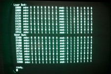
(1) With all the RAM on the motherboard enabled, the standard edit ROM won't boot (black screen, no chirp), and PETTEST fails the zero page test. Every 64th byte in the zero page test is correct however (I've been trying to wrap my brain around what that could mean, as far as stuck address lines or stuck RAM bits or what not?) Here's a photo of the zero page test results:
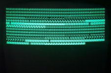
zeropagetest.jpg

(2) With zero page ($0000 to $03FF actually) mapped to the ROMulator and the rest of the RAM on the motherboard enabled, the standard edit ROM boots, but BASIC reports 0 bytes free. PETTEST reports 4K, and then:
0..........
mem fail 0 0 0400 02 0f!

(3) With zero page and the rest of the first bank of RAM mapped to the ROMulator and only the second bank on the motherboard enabled, the standard edit ROM boots, but BASIC reports 15359 bytes free. PETTEST reports 16K, and the 16K passes tests.

So it seems like I either have problems with both banks of RAM, or possibly with the 74LS244 chips that handle RAM addressing, CAS, and RAS (UE8, UE9, and UE10)?

This is where I hit the limits of my knowledge. I do have a scope (that I barely know how to use, lol), and looking at the above chips and the RAM chips, I see "stuff" that looks normal to me (-5, +5, +12 where it should be, and activity on all the other pins that are shown connected on the schematics.) Some of the levels look low, some even a tad below 4V, but that should still be within TTL specs I think? None of the lines appear to be stuck in a high or low state.

Is there a way to troubleshoot this further without resorting to desoldering all those chips? I do have a proper desoldering iron (that I barely know how to use... there's a pattern here, lol), but that's 316 pins, if I did my math right. :)

PETTEST's RAM test will provide enough detail to identify which specific RAM chip is causing a problem, but unfortunately it won't even test the RAM, because it's failing badly enough that PETTEST doesn't recognize it (PETTEST simply does a write/read test on the first byte of each bank to determine if there is RAM there to test, and since mine fails, it thinks there's no RAM there and won't do a detailed test of it.) Is there a better RAM test program I should use?

Thanks for any ideas!
 
A quick update and correction:

The correction is that because I had a DIP switch on the ROMulator set wrong, the error at $0400 that I listed in my original post should not have occurred at that time. I should have had the RAM at $0400 on the PET disabled at that point, but I did not. So disregard that.

The update is that I figured out a way around not being able to get PETTEST to run: I realized that since the ROMulator can map memory to/from itself on a page by page basis, I could just map the 4 pages that PETTEST uses to detect memory ($0F00, $1F00, $3F00, and $7F00) to the ROMulator, and indeed, that worked. It forced PETTEST to see that there was memory present and test it.

So having done that, and used that method to test a few different pages throughout both RAM banks, I consistently got the following:

Bank 0:
mem fail 0 0 XXXX 02 0f!
Bank 1:
mem fail 0 0 XXXX 02 0e!

(With XXXX being the page I was testing of course.)

I'm puzzled as to what that last byte means. According to the PETTEST docs, it's the byte it got back when reading from the address, but that doesn't make sense to me since PETTEST is supposed to write all zeros during the first test, and yet it's only reporting one bit being stuck?

So it looks like bit 2 is stuck on in both banks. Bit 2 maps to UA16 and UA17. Does this mean these two chips are most likely bad? Does bit 2 being stuck on correlate to the "every 64th byte is correct" error I was seeing during the zero page test? I believe that test uses an incrementing value, so if every 64th byte has bit 2 on then I guess it would make sense. I need to go get a PETSCII table out and look at the bits after I finish writing this, I'm still having trouble wrapping my brain around that.

Since these two chips are both on the same data line and physically right next to each other I'm also going to double check to make sure there isn't a broken trace or failed decoupling cap.

I'll post another update when I have one. Unfortunately I'm still on moderated status because I'm new here, so it can take a while for my posts to get through.
 
Welcome. I hope your PET RAM debug odyssey is shorter than mine.

My understanding of the two messages you get there is the same as yours for Test 0 in the PETTESTER. Hopefully the author, Dave, will be able to offer you some insight. He has been super helpful to me, although I haven't been able make that bear fruit yet.

Cheers,
Greg
 
Thanks Greg!

Well, I'm thinking now that PETTEST is just reporting the *first* bit error that it sees, even if more than one bit in the byte is wrong, and that I probably have more than two bad RAM chips (or something else is wrong), thus the different byte values.

I poked around with my meter and toned out all of the pins on both of the suspect RAM chips today, and they all checked out ok, so there aren't any broken traces. After some Googling I realized that I don't have the gear needed to test capacitors in-circuit (i.e. an ESR meter), but I very much doubt those decoupling caps are the issue due to some more testing I did...

I was still having trouble wrapping my head around the "every 64th byte is correct" phenomena, so I mapped just enough pages to the ROMulator to get the PET to boot into basic, then I wrote a simple basic program to poke/peek a few random addresses in each bank and print the results. I've ran it a number of times and the results are consistent:

petmemtest.jpg

Looking at this, it looks like I have bits 0,1 stuck ON in bank 0, and bits 1,2 stuck ON in bank 1. Bit 3 seems stuck OFF in both banks, and 2,4 in bank 0 are intermittent.

Soooo... I either have at least *eight* bad RAM chips, not two as I initially thought based on PETTESTER. Either that or there's something else in play here?

The RAM in mine are all ITT 4116 3N's, with 1981 date codes. Is it common for this many of these chips to go bad? I don't know anything about the history of this particular machine, but it doesn't look like anything on it has ever been reworked.

I guess I'd just like some opinions before I start desoldering stuff. I need to order some sockets and RAM chips before I do, so it will be a while before I get started. I suppose I could start by just replacing one of the chips that appears to be stuck on, now that I have a consistent way to test things, and see if that gives me the expected results. If it does then I can go ahead and replace the rest.

I'm really surprised that (at least) half of the chips could be bad though! Yikes, what were these made out of? :)
 
I've heard that 4116s can be fragile, but I haven't found a definitively bad one myself yet. It's a possibility that many of them are bad, but it seems like low probability unless something bad happened all at once like the board getting zapped.

Regarding decoupling caps, I think that's also unlikely. Usually you only get problems there if a bunch of caps go bad and even then the failures are more random. At least that's been my limited experience.

I thought about the "every 64th byte" pattern you're seeing, and that seems more telling to me. Perhaps something is wrong with address line 5. However if it was stuck I'd expect to see a string of 64 failures (making the naive assumption that the address bus is just counting up, which it isn't -- there are instruction fetches from ROM in there which seem to be working ok.) It would have to be something sensitive to a change on an address line. Looking at the schematics, there doesn't seem to be anything explicitly designed to do that. However, that address line is connected to a PIA, the ROMs, video address mux and RAM address buffer. The ROMs and the PIA are also connected to the data bus. Could a transition on an address line be causing one of those to glitch the data bus? Does the behavior change if you swap the PIAs? Can you burn a spare set of ROMs and see if that helps anything? Do the transitions on the address lines look nice and sharp? Maybe a slow transition on A5 is causing the address to not be stable when it comes time to read or write? Of course, most of what I describe here should also be true of reads from the ROMs and writes to the display RAM. Those seem to be working ok, so it's probably not something the RAM subsystem shares with the ROMs or display. Which brings us back to the RAM address buffers and RAM chips themselves. The RAM address buffers (74LS244s) seem like the greatest opportunity for a single point of failure, so I'd very carefully look at those.

Incidentally, a NOP generator is super helpful for debugging address bus issues. It just makes the CPU address bus into a a big 16 bit counter, so it's easier to see if the bit patterns on the address bus make sense. Do you have one or can you build one? There's several easy to find guides to building them online.

I'm just brainstorming here and you probably know more than me and have definitely thought about it more than me. This is my first time looking at the 8032 schematics. I haven't even been able to fix my PET 2001 yet, so everything here should be taken with a big grain of salt.

Good luck,
Greg
 
Welcome to the world of fixing PETs with the most horrible of faults - DRAM :)!

Yes, my PETTESTER halts and reports the first error it finds - however, there is a caveat to this. When it detects a fault - it has to re-read the data byte that caused the fault to report it. So, intermittently faulty RAM can either (a) test OK and then read bad or (b) test BAD and then read OK. I may have to get around to fixing that at some point. It is not a problem with the test code - but with the reporting code. I may need to re-write this entire thing though - hence my reluctance! I am trying to use as much stuff as possible within the CPU registers - to avoid a RAM fault from clobbering the RAM test itself. Unfortunately, the only way to form 1 16-bit pointer in a 6502 is to store the 2 bytes in RAM and indirectly address them. This is why the RAM test can (itself) crash. I should be able to improve things by using a better initial page 0 and 1 RAM test - but I can't 100% avoid it though.

The reason it halts on the first error is one of convenience. My plan was to print as many errors out as would fit on the screen. However, in the interest of getting something out that was usable, I opted for the simple 'one shot' reporting first. Plan is to add more reports later. I could also use the keyboard to perform the equivalent of a 'clear screen' and move on later. However, the keyboard mapping is completely different between versions of the PET. I want one simple version of the PETTESTER that will run in all PETs. So far I have managed this (with one exception - a 40 column CRTC PET). This requires a couple of changes to the CRTC initialisation table.

You get the source code - so you can make as many changes to the code as you like!

The memory tests treat the memory as a 'sea of bits' and not bytes. This is how the standard MARCH memory tests work. The 'all 0' and 'all 1' tests use the underlying MARCH bit manipulation and test routines - hence you can have multiple bit errors within the byte - but only one reported. Compound this with the test and report issue I have already mentioned.

Anyhow, back to your specific problem.

You need to not only check the dc voltage levels with a multimeter - but also check for noise with an oscilloscope. You should also do this at various points over the board. What oscilloscope do you have (make and model)?

The first step with a memory fault is to construct a piece of test equipment called a NOP generator. This allows us to use the oscilloscope to follow the address lines from the CPU through the various buffers and address decoding to the RAM. Have a look on the internet (or read a few of the threads here) and ask any questions you may have.

I think you have multiple faults incidentally - which increases the hassle factor. If you ignore the 'every 64 bytes' issue - you should see a pattern every 16 or 32 bytes (16 uparrows in a line. 32 'z' in a line. 16 '>' in a line). This could indicate an address fault, a data fault - or both... My money would be on a RAM address multiplexer fault (but that is purely a guess).

We have seen DRAM chip faults, data bus buffer faults and RAM address line multiplexer faults.

I don't like replacing a chip unless I know it is actually faulty - or if there are no other tests I can perform to say it is good. Some people prefer the 'scattergun approach' and replace a chip if any test even remotely indicates a potential problem. Sometimes they are lucky. Most often they end up with a pile of desoldered good ICs and the same fault... Their view is that they think they are making progress by doing something rather than not. I prefer the 'slow and steady' approach myself.

Incidentally, are you repairing this machine to keep or sell? Not that it matters to me one bit - you will still get the same advice. But if you are going to sell it, keeping it in the most original state would be the best way to go.

Dave
 
Last edited:
I thought about the "every 64th byte" pattern you're seeing, and that seems more telling to me. Perhaps something is wrong with address line 5. However if it was stuck I'd expect to see a string of 64 failures

Well, I've poked around at all the address lines - the actual CPU address lines, the buffered lines, the lines on the other side of the RAM address buffers going into the RAM itself, and the lines going into the refresh address decoder (I think that's what it's called), from the address counter in the master timing circuitry. None of them are stuck high or low, and as best as I can tell, what I'm seeing on them looks normal, although the voltages are a bit low as I've mentioned before (I think within TTL tolerances though?)

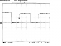
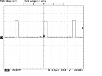
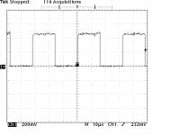
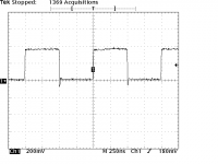
Here is FA5, BA5, RA5, and CLK1B (the clock that drives the RAM refresh). You'll note that I have my y-axis scaled wrong, because I'm a oscilloscope noob, lol. :-D Pretend it's set to 2V/division though, and you can see that most of the signals are just a bit under 4V:

FA5:
tek320-capture-20210203-150535-FA5.png

BA5:
tek320-capture-20210203-152219-BA5.png

RA5:
tek320-capture-20210203-152331-RA5.png

CLK1B:
tek320-capture-20210203-151218-CLK1B.png

Does the behavior change if you swap the PIAs?

Unfortunately the only chips on my board that are socketed are the Character and Edit ROMs, and the CPU, so it isn't easy for me to swap them. I do have a desoldering iron though so I can remove them if I need to, I just don't want to start hacking up the board until I'm sure I've done all the other troubleshooting I can first. It's a good idea though; if I swapped them and it changed to a different error frequency then we would know it was one of the PIAs. I wish they were socketed.

Can you burn a spare set of ROMs and see if that helps anything?

I could, but the ROMs all seem to be working properly (if I map the RAM to the ROMulator board but leave all the ROMs on the PET enabled, the PET boots up and works normally.) Also, I can map any of the ROMs out to ROM images on the ROMulator and everything works fine that way as well. I'm also able to use the IEEE-488 port, cassette ports, and the few pins I've tested on the user port (bit-banging a serial connection). Everything really seems to point to the RAM (or related circuitry.)

Do the transitions on the address lines look nice and sharp?

Well... umm... uhh... "I'm new here". :-D (I'm not really sure what they should look like or what would constitute sharp, but they all seem pretty much like the samples above... ("sharpish"?) :) I see some undershoot and levels are a bit low, and they're not perfectly square waves, but I think they're ok?)

Which brings us back to the RAM address buffers and RAM chips themselves. The RAM address buffers (74LS244s) seem like the greatest opportunity for a single point of failure, so I'd very carefully look at those.

Thanks, I've been starting to lean in that direction as well. It seems unlikely that so many RAM chips could fail (although like most PETs, this one's history is unknown, so it could have gotten zapped or something as you said.) I feel a bit more confident now, since we're both coming to the same conclusions.

Incidentally, a NOP generator is super helpful for debugging address bus issues. It just makes the CPU address bus into a a big 16 bit counter, so it's easier to see if the bit patterns on the address bus make sense. Do you have one or can you build one?

I don't have one, but I actually just learned what one was a few months ago whole watching a video on youtube about how to hardwire up a 6502 on a breadboard, so I think I've been secretly looking for an excuse to build one. ;-) There may even be a way to make the ROMulator that I have act as one. Or I could just build one.

I'm just brainstorming here and you probably know more than me

That's a bold assumption, lol. (I certainly know enough to get myself into trouble, not always enough to get out.) :)

I haven't even been able to fix my PET 2001 yet, so everything here should be taken with a big grain of salt.

I noticed that thread but haven't had a chance to read all the way through it yet, there are so many replies. I'll try to get through it and offer ideas if I have any, although I probably won't. I spent nearly three decades doing IT, but it's really only been very, very recently that I've started getting into the electronics side of it, just for fun. I'm learning a lot though. Happy to help out if I can.
 
Welcome to the world of fixing PETs with the most horrible of faults - DRAM :)!

Thank you! Ummm.... I think? Hehehe.


You get the source code - so you can make as many changes to the code as you like!

Excellent, I just have to learn 6502 assembler first, should only take a few minutes. ;-)

But seriously, PETTESTER is excellent, thank you for creating it, and for documenting it so well. Because you actually documented exactly how it goes about detecting what RAM to test I was able to map just those page out with the ROMulator to force it to run the RAM test.


You need to not only check the dc voltage levels with a multimeter - but also check for noise with an oscilloscope. You should also do this at various points over the board. What oscilloscope do you have (make and model)?

I posted some scope captures in my response to Greg a moment ago, but I'm still on moderated status so I'm not sure if it will be visible when you read this or not. I don't have enough experience to know what constitutes a noisy signal. To my novice eyes they look ok, but I'd really appreciate your opinion.I have probed various other points on the board and haven't seen anything that looks too crazy, just the lowish voltages I mentioned. (Which I noticed on the scope, not on the multimeter, but I did check all the power rails with my multimeter and those are all good as well.)

I have a Tektronix TDS320, which I bought off of Craigslist last year for $100. :) It's pretty old (mid-90s?), but does the job. This is literally the first thing I have ever used it for beyond measuring a test signal.

The first step with a memory fault is to construct a piece of test equipment called a NOP generator. This allows us to use the oscilloscope to follow the address lines from the CPU through the various buffers and address decoding to the RAM. Have a look on the internet (or read a few of the threads here) and ask any questions you may have.

Thanks! I just mentioned to Greg in my reply to him that I recently learned about NOP generator and was kindof looking for an excuse to build one, so should be fun. :) This of course is a part-time hobby for me, so it may be a little while but I'll post back when I have one ready.

I think you have multiple faults incidentally - which increases the hassle factor.

Story of my life. :)

If you ignore the 'every 64 bytes' issue - you should see a pattern every 16 or 32 bytes (16 uparrows in a line. 32 'z' in a line. 16 '>' in a line). This could indicate an address fault, a data fault - or both... My money would be on a RAM address multiplexer fault (but that is purely a guess).

I'm thinking that as well, simply because everything in the PET seems to work properly except the RAM (which wouldn't be the case with address or data lines were stuck), and because it seems unlikely to me that so many RAM chips could be bad.

I don't like replacing a chip unless I know it is actually faulty - or if there are no other tests I can perform to say it is good. Some people prefer the 'scattergun approach' and replace a chip if any test even remotely indicates a potential problem. Sometimes they are lucky. Most often they end up with a pile of desoldered good ICs and the same fault... Their view is that they think they are making progress by doing something rather than not. I prefer the 'slow and steady' approach myself.

Oh no, I'm with you 100%! I don't want to desolder anything until I'm certain I've done all the non-destructive troubleshooting I can. The board does not appear to have ever been reworked, at all, so I don't want to start going around hacking it up willie-nillie.

Incidentally, are you repairing this machine to keep or sell? Not that it matters to me one bit - you will still get the same advice. But if you are going to sell it, keeping it in the most original state would be the best way to go.

I have no intention of ever selling any of my vintage machines. :-D That having been said, I would still prefer to keep it as original as possible, within reason. If I replace a chip I'll put a socket in of course, I'm not that much of a purist, but I just don't want to start hacking it up more than I need to.

Thanks!
 
Hi xenium,
Depending on when you got the ROMulator, there should be a NOP generator at index 12, which is 1 off, 2 off, 3 on, 4 on. If not, installing the latest build would give you that setting.
 
Back
Top