• Please review our updated Terms and Rules here

Epson QX-10 Power Supply Diagnosis

smbaker

Experienced Member
Joined
Oct 21, 2016
Messages
434
Location
Oregon, USA
I've decided to take on a known-bad Epson QX-10 as a project. I have verified the power supply fuse is not blow, and AC is reaching the power supply board and at least making it past the input filtering. There's no DC produced at the output. Condition of this unit is pristine, not quite unused but really clean. Absent anything else, I'll pull the PSU and start scrutinizing the electrolytics.

I've read there was a Sam's Computerfacts that included a power-supply diagnosis section. It looks like it was available online at some point, I found some dead links leading to dropbox from a site called "yesterbits.com". I don't suppose anyone has a copy, do you?

Thanks,
Scott
 
I have both the file for the mainboard, psu, keyboard, and the graphics board that I used while repairing my QX-10. I've uploaded them to google drive here:

https://drive.google.com/drive/folde...Kt?usp=sharing

If this link doesn't work, let me know and I'll try Dropbox instead. Good luck repairing, these are very cool CPM machines!
 
Last edited:
Thanks. I found a bad resistor R2, replaced it, and it instapopped the replacement resistor. Checking IC1, the STK711 regulator, there's only 1 ohms between pins 11 and 15 (SAMS guide says to check for a "short", and that seems pretty close to a short). So I'm thinking it's a bad STK711.

Now my question is, do I grab a $30 modern meanwell power supply and substitute it, or do I spend $16 on a replacement STK711 and see if that's the end of the trouble? I can see pluses and minuses to going either way. It's nice to keep it original, but on the other hand, a power supply is the least interesting part of a computer.

If find it a little strange the fuse didn't blow. You'd think the fuse would give its life before a 5W resistor does. I did check and the fuse is rated correctly.

Scott
 
I'd keep testing for faults closer to the mains plug to make sure it's not something upstream. If not, i'd fix it. I had to replace mine to get mine to function.
 
Looks like there's quite a few outputs from the pwr supply and replacing it with a single or even two Meanwell supplies might be a problem. You'd need at least +/-5 and perhaps +/-12 and then see if you can strap the various outputs of what appears to be the same voltages together. But I understand problem spending a bucks on a chip just to see if you can let the magic smoke out of it in the troubleshooting process. I did replace a simple +5 and +24v linear supply with a meanwell in an S-100 system because the original supply had no protection in it's design and failed with an over voltage spike to the floppy drives.
 
I got a qx-10 the other day and I'm trying to connect the monitor, I think I found the cable (Din 8 to din 7) but it doesn't seem to do anything, I'm trying to verify the pinout of the cable but the only online guide is confusing, and doesn't say if it's the male or female pinouts.. grr.


Any chance of you pinning out your video cable?

Thanks.
 
Do a google search for the Epson QX-10 service manual and there's a pin out of the QX-10 video connector. I had to modify a QX-10 monitor to use on a QX-16 and there's only 3 active wires plus ground inside the CRT monitor. One is +12VDC that is supplied from the QX-10 and then there's the video signals. The +12vdc is missing on the video cable if it is plugged into a QX-16 since the correct OEM monitor for the QX-16 had its own internal pwr. supply. So make sure you have a QX-10 and not a 16.
 
I thought about your problem some more. There's a bank of switches on the rear of the QX-10 and they need to be in the correct positions or no video. Left most DIP switch (#1) should be down and the rest should be up.
 
My QX-10 originally didn't have a video cable and I had to order one online. It arrived with the correct din plugs but a completely incorrect pin-out, including sending the monitor's 12V power down one of the sync lines! Thankfully, it didn't damage my monitor, but it means I had to do some video cable work to get my QX-10 displaying properly. I rewired my cable according to this diagram and it works perfectly:

https://fjkraan.home.xs4all.nl/comp/qx10/cable3.gif


This pin-out is for male din plugs on the cable itself. The colors of your wires may not be the same, but I verified that the image has the correct pin-out to get a working QX-10 video signal compared to my working cable (testing the pins on both sides in continuity mode). There are also some jumpers on the video card to set the correct amount of present video ram alongside the switches on the back of the computer. Make sure your brightness on the monitor is turned up with the pot on the back as well, you should get an "insert diskette" message on power-up. Hopefully this helps!
 
Looks like there's quite a few outputs from the pwr supply and replacing it with a single or even two Meanwell supplies might be a problem. You'd need at least +/-5 and perhaps +/-12 and then see if you can strap the various outputs of what appears to be the same voltages together. But I understand problem spending a bucks on a chip just to see if you can let the magic smoke out of it in the troubleshooting process. I did replace a simple +5 and +24v linear supply with a meanwell in an S-100 system because the original supply had no protection in it's design and failed with an over voltage spike to the floppy drives.

I'm only seeing +5, +12, and -12. No -5. While there are multiple 12V rails (3 of them, one each for logic, FDD, and monitor), I'm thinking about driving them from a single supply together with some LC filtering to reduce interference. According to the schematic, it looks like all rails share a common ground.

I tried replacing the STK711 last night with no success. Either the new one I received is bad, or there's something else wrong.

Scott
 
I guess as long as the supplies can handle the needs of the circuits then you'll be okay. I needed to modify a QX-10 CRT monitor for use with the QX-16. The difference is that the QX-10 supplies the +12v to the monitor to power it up via the video cable and the QX-16 CRT (extremely rare) had a power supply with AC cord. I checked the current needs of the monitor and saw about 3/4 amp when in use. I'm using a 1.5 amp brick to power the monitor, since it was easy to purchase and cheap, and it has been working well. If you figure about 1 amp or more to be safe to your +12 needs and you should be okay. I believe the service manual claimed 1.25 or 1.5 amps.
 
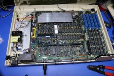
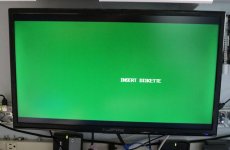
I've had some success. Two pictures are attached. The first is the relatively small meanwell supply mounted in the QX-10 case. I still have a PCB coming that's going to add some LC filtering for the multiple 12V rails. The supply is a bit under spec -- according to the tech manual, the sum of the 12V rails is about 2.5A and the supply is only rated a maximum of 2.2A. It might still be fine, and almost certainly is fine if I don't attach a "real" monitor. The second picture is from a modified MCE2VGA. I haven't had a chance to try to tune it yet, so I may well have the picture offset or scaled inappropriately.

Click image for larger version  Name:	qx10-psu-640.JPG Views:	0 Size:	129.5 KB ID:	1211643

Click image for larger version  Name:	qx10-mce2vga-boot-640.JPG Views:	0 Size:	53.9 KB ID:	1211644
 
If you need to reduce the +12 load, and are going to use the QX-10 CRT in the future, you could do the QX-16 mod to the CRT and just power it from a wall wart. Mine works fine from a cheap AC adapter bought on eBay for my QX-16. Let me know if you want a boot diskette.
 
If you need to reduce the +12 load, and are going to use the QX-10 CRT in the future, you could do the QX-16 mod to the CRT and just power it from a wall wart. Mine works fine from a cheap AC adapter bought on eBay for my QX-16. Let me know if you want a boot diskette.

I suppose I should try writing some of the images I found online. I actually have a project where I married a 360K floppy drive to a raspberry pi and can use it to write floppies. What threw me a little was that a bunch of the QX-10 disks I found appear to be 16 sectors per track for the first two tracks and then 10 sectors per track for the remaining tracks. That isn't something I imagined, or had coded for. Maybe I'll just boot up a DOS machine and run ImageDisk.

Let me try it tonight and then let you know if I succeed.

Scott
 
I was able to burn some images with ImageDisk using a DOS machine and I *think* the images are good. The QX-10 though still sits there are the "INSERT DISKETTE" prompt. I can't really get any indication that it has recognized a disk has been inserted, or that it's attempting to read it. I did pull the drives tonight and give them some TLC -- there was old grease that had solidified and was sticking the ejector mechanisms. That didn't seem to help.

Next weekend I might try pulling the drives and bench testing them, at least get some confidence that the drives are working properly.

Scott
 
This machine still stubbornly resists getting past "INSERT DISKETTE". The heads are not seeking, and the drives do not appear to be selected. I did pull the system board and found nearly all of the electrolytics leaking. One of them had sufficiently leaked that it led to destruction of one of the traces. Recapped the system board over the weekend, and it's still not happy. Next is to try swapping the FDC chip, and if that fails, there are some SAMS steps to check clock frequencies and such. I did swap the drives, and confirmed it's not a problem with the drives themselves.

On a positive note, fellow forum member dabone did send my way a complete functional QX-10. It's a cute little machine; I'm feeling this is one I'm going to have to find a practical use for. Maybe finding (or writing) a CP/M BBS would be a fun exercise.

Regardless, I'm still committed to solving the mystery of the misbehaving original unit.

Scott
 
If you have the original QX disk drives, do you know the secret to making them function? For $20 (just joking) I'll give you the secret password --> the Epson drives require you inserting the diskette and then pressing the disk release button. Yes, to load a diskette you press the button. Else the diskette isn't seen. Press once to load, press a second time to pop out.

Also, if you suspect the "A" drive is not working you can swap the drive cables at the mobo and have the right side drive become drive A. My QX-16 came with the drives reverse in this manner.

Also, PM me your address and I can send a known good boot diskette to you.
 
Also, if you suspect the "A" drive is not working you can swap the drive cables at the mobo and have the right side drive become drive A. My QX-16 came with the drives reverse in this manner.

Also, PM me your address and I can send a known good boot diskette to you.

The drives themselves are working when migrated to a different QX-10, and I have a working boot diskette. If you happen to have a C compiler (does one exist?) or Turbo Pascal for the QX-10 (did Borland ever make that?) then I would love to have one of those.

So far every QX-10 drive I've received has had some kind of issue with the ejection mechanism. Lubricant seems to dry out inside and stick the mechanism.

Scott
 
Yes, my drive A was sticky when I first got my QX-16 up and working. It is still a bit touchy at times, but has improved with use. I don't know of a "C" compiler made just for the QX, but any CP/M C compiler should run on a QX. Ditto for Turbo P. Lowe's sells a replacement clock battery that you have to order online. Details in a post I made in the Epson QX group here on VCF. There's a 1MB expansion RAM card for the QX-10 on eBay at the moment if anyone wants to spend money. The QX-16 came with more memory and I'm not buying it.
 
Back
Top