• Please review our updated Terms and Rules here

Osborne 1 Repair

willseward

New Member
Joined
Apr 27, 2018
Messages
5
Location
Fort Worth, TX
Hello,

I bought an non-working Osborne off EBay in hopes of repairing it in my spare time, but I seem to be way in over my head in terms of debugging prowess. I'm curious if I could get a little bit of help.

The symptoms are as follows:
  • Won't boot
  • Beeps continuously
  • CRT shows boxes and random characters

I've been poking around with a scope and found a few oddities. I'm no electrical engineer, so I could be barking up the wrong tree...

So far I've replaced the Z80A, the '393s in A13 and B14, and the '175 in D14 to no avail. I chose to replace those on a hunch after looking around with my scope. I've included a few photos of the waveforms I think seem problematic.

Any way, any suggestions or tips would be appreciated!

Thanks!
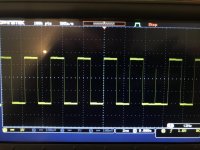
IMG_0072.jpg
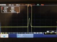
74LS393 in B14 : pin 12 (CLK)

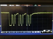
IMG_0073.jpg
74LS393 in B14 : pin 11 (2Q[SUB]A[/SUB])
Notice the "blip" that only lasts a few ns.
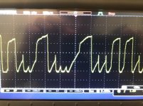
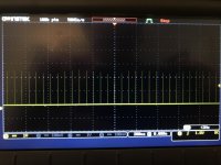
IMG_0074.jpg
MCM4116 : pin 2

IMG_0075.jpg
Z80 : pin 24 (WAIT)

IMG_0076.jpg
74LS175 in D14 : pin 7 (Q[SUB]1[/SUB])
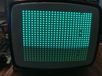
IMG_0079.jpg
CRT
 
Could be almost anything, but my hunch would be RAM. Those 4116 chips are not the most reliable of things. In memory mapped devices like these, bad RAM can make the machine exhibit all kinds of crazy behaviour...lights flashing...drives on...screen with garbage on it.

Tez
 
I figured that much. I have 12 4116s on-hand, but I can't find a faulty IC by piggy-backing the chips. Do you know the typical failure mode of the component?
 
It's always difficult to pinpoint failed 4116s unless they're burning hot. Before blaming RAM chips though make sure the PSU is ok. The Osborne 1 uses an Astec AC8151 variant putting out +12/-12/+5. The -12 gets regulated down to -5 for the RAM chips so if you don't have -12 you'll be in trouble. Check the 4116s for -5V on pin 1, +12 on pin 8 and +5 on pin 16.

I know this won't help you in the short term but I got fed up tracking down dead 4116s in Commodore PETs so I built a tester using a ZX Spectrum. I put a ZIF socket on the left-most lower RAM location and use Benny Alford's diagnostic ROM. I can get through 16 4116s in a few minutes.

That's a really good suggestion. I have another osborne, so I might stick a ZIF on that one.

Thanks!
 
@Witchy: I did the same as you, testing DRAM on a ZX Spectrum. One of the DRAMs I tested blew the Spectrum up! I think it damaged the power supply but haven't got round to repairing it yet.

I'd suggest the OP proceeds with caution on this one - be ready to disconnect the Spectrum's power the moment you see it has failed to boot. In my case I left it running for a few seconds before it blacked out.

As the OP is in the US, he may find it difficult to procure a Spectrum. The US version was marketed under the name Timex Sinclair 2000 series.
 
Last edited:
Building this will be well worth the effort in the time it saves you.
https://fjkraan.home.xs4all.nl/digaud/arduino/Z80exer/

I built one and used it to repair a trso80 model 1 with multiple faults that was proving very difficult to diagnose using normal methods. I have modified the code and laid out a shield pcb and schematic so it will using via the CPU socket or the model 1 expansion connector.

Pair it up with a $10 logic analyzer off ebay and locating faults becomes easy. Instead of the confusing oscilloscope signals you see clean signals of just the operation you specify with no extraneous signals to confuse the issue.

It takes about 90 mins to wire up and get working
 
That looks pretty nifty, particularly if it can pinpoint stuck RAM chips. Pity I don't have a spare Arduino Mega.
 
Building this will be well worth the effort in the time it saves you.
https://fjkraan.home.xs4all.nl/digaud/arduino/Z80exer/

I built one and used it to repair a trso80 model 1 with multiple faults that was proving very difficult to diagnose using normal methods. I have modified the code and laid out a shield pcb and schematic so it will using via the CPU socket or the model 1 expansion connector.

Pair it up with a $10 logic analyzer off ebay and locating faults becomes easy. Instead of the confusing oscilloscope signals you see clean signals of just the operation you specify with no extraneous signals to confuse the issue.

It takes about 90 mins to wire up and get working

that is fantastic. I didnt know about this. One more project I need to build.
 
I just laid out and ordered a shield that will plug directly into the Mega2560. I should have 20 bare boards in a little over a week.
The shield I designed supports both the standard z80 cpu socket and the TRS-80 Model 1 expansion edge connector, I've modified to original code to support both.

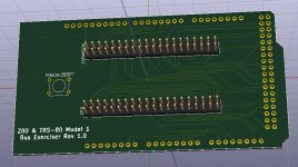
The board will look something like this.
Untitled-1.jpg
My component library didn't have a 3d model for the push button and the pins that plug into the arduino are missing, but you get the idea.
You just need an Arduino Mega2560 ($10 on ebay) and to make the appropriate ribbon cables I'll be making the code available once I add a few enhancements.
At this stage I expect I'll sell a bare board for about $10.
 
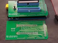
The boards have arrived and work as intended, however there is a small issue with the silk screen I didn't foresee. When using boxed headers the the header description is covered.
It's annoying and I'll update the silkscreen if i do another run but no so big a problem that I'm inclined to run them again for that reason alone.
20180628.jpg
 
thats too bad, if you had a good amount of boards printed, just have the buyers mark them prior to building. Little details like that are annoying arent they?
 
thats too bad, if you had a good amount of boards printed, just have the buyers mark them prior to building. Little details like that are annoying arent they?

Yes, mark it or just dont use boxed headers.

Anyone that still wants one, PM me your address and I'll let you know the postage cost.

As a bonus I'll include a push button switch with each board.
 
David,
I noticed that there is no Silkscreen for Pin 1 marked outside the boxed header too. It's easy to see the square pad in the photo,
but after the header is installed it won't be so easy to see that pad.

Thanks.

Larry
 
I happened to find this project while browsing around: https://github.com/hoglet67/AtomBusMo/. Seems to be able to do similar things compared with the Z80exerciser linked to earlier but also include softcore of the processor. In Circuit Emulator. Fascinating that ICE systems that used to be pretty expensive now can be implemented on cheaply available FPGA boards.
 
Back
Top