• Please review our updated Terms and Rules here

M8652 KL8F Double-buffered asynch terminal control

thunter0512

Veteran Member
Joined
Sep 27, 2020
Messages
859
Location
Perth in Western Australia
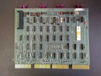
Has anyone got the manual and/or schematics for the M8652 UART board?
It is PDP-8/e option KL8F.

Here is a photo:
IMG_20210523_114147652.jpg

Thanks and best regards
Tom Hunter

P.S. This new Vcfed vBulletin Version 5.6.4 does something strange when uploading photos. I have to compress all detail out of the JPEG image to so that it allows me to upload it. Nominally it has a 256 kb limit but it refuses to upload files much smaller. It seems to be doing some post-processing which blows the files up to a larger size. It is impossible to predict what that size will be so I struggle with the 256 kb limit. It would be better to disable this post-processing but who do I talk to for any website suggestions?
 
I don't have one of these so I have never looked for the documentation for one. I only show having two M8655 boards in my inventory. I also have an M8319 which is a quad serial interface for the 8/a (hex width board). I have been looking for an M8650 but those are the non-uart version of the board and can be lightly modified to go faster than 9600 baud which makes them desirable for serial disk use.

I did find a maindec for your board on Vince's site
http://svn.so-much-stuff.com/svn/trunk/pdp8/src/dec/maindec-08-dhklc/
and a photo of the corner of a drawing for the board on the Datormuseum.se site.
http://forum.datormuseum.se/item/CC189436-0AC1-4F29-A2FF-D688E886F878.html
Which means they have something.

What UART is that? The photo isn't clear enough to read.

I was on the fence about the new forum software but I have decided that I don't like it. In trying to make it easier to use the functionality has decreased.

Disk is cheap. Let us upload large photos!

Doug
 
Has anyone got the manual and/or schematics for the M8652 UART board?
It is PDP-8/e option KL8F.

P.S. This new Vcfed vBulletin Version 5.6.4 does something strange when uploading photos.

I can create an Eagle project for the board and host high-res photos of the front and back, if you've got them. And Engineering drawings, if you find them.

Finishing the reverse engineering would be quite a time-sink, tough, so I can't promise that. It doesn't look all that complicated, though.

Vince
 
I don't have one of these so I have never looked for the documentation for one. I only show having two M8655 boards in my inventory. I also have an M8319 which is a quad serial interface for the 8/a (hex width board). I have been looking for an M8650 but those are the non-uart version of the board and can be lightly modified to go faster than 9600 baud which makes them desirable for serial disk use.

I did find a maindec for your board on Vince's site
http://svn.so-much-stuff.com/svn/trunk/pdp8/src/dec/maindec-08-dhklc/
and a photo of the corner of a drawing for the board on the Datormuseum.se site.
http://forum.datormuseum.se/item/CC189436-0AC1-4F29-A2FF-D688E886F878.html
Which means they have something.

What UART is that? The photo isn't clear enough to read.

I was on the fence about the new forum software but I have decided that I don't like it. In trying to make it easier to use the functionality has decreased.

Disk is cheap. Let us upload large photos!

Doug

Didn't remember that I had that document. Good that google remember.. I will pay a visit to my father this weekend (where all things are located) so I can try to find it. Unfortunately I have not access to any ledger size scanner these days. I hope decent quality photos will do?
 
What UART is that? The photo isn't clear enough to read.
Doug

There are two lines of text on the UART:

AY-5-1012
GI7330

The "GI" stands for "General Instruments".

I found the datasheet for the AY-5-1013 and it may be similar enough. It seems quite suitable to implement the PDP-8/e terminal interface with all the configuration bits directly exposed on pins (i.e. bits per character, parity selection and stop bits).

Thanks Mattis - some photos of the manual or schematic would be great.

Best regards
Tom Hunter
 
I remember the AY-5-1013 but not the 1012. I found a data sheet for the 1013 easily but the 1012 is more difficult. I did find a reference to the 1012 in a Don Lancaster article about UARTs. From his description it looks the same as the 1013 but he either didn't bother to connect the 8th bit or the 1012 is only a 7 bit part. The 1012 and 1013 needed -12 and +5 volts. Later versions went to 5 volt only leaving the -12 pin unconnected.

The 7330 in the GI7330 is the date code for 30th week of 1973.

I hope Mattis can find the document and make good images for you.
 
There was just a two page schematic.

https://drive.google.com/drive/folders/1-F9EcGZJMqON4RIzzyPBCXvfO9Gb4ilN

Don’t know if there is a manual. But there are plenty of documents to get into the inventory. If someone feel like staying in the Swedish countryside for a while going through huge amounts of DEC documents there is nice little cottage to stay in. Free of charge of course.
 
Back
Top