• Please review our updated Terms and Rules here

PDP-8/E front panel problem

Are the addresses on the bus actually working correctly, and it the problem is just with the addresses that are displayed?

There is some really complex IC logic and diodes to control the lights. If one diode is shorted you will get some interesting behavior because a one or more lights will be enabled by multiple signals, including signals that should be disabled.
 
You could do a LOAD ADDRESS and sequence the switches to see if the right pattern gets displayed on the lights.

The initial LA pf 0000 didn't change the address display to 0000. The diode idea is interesting, but that should affect the bottom row. The top row should be driven by E16 and E20.

Oh, wait! The 7416 buffer at E19 drives exactly the lamps reported to be the problem.

Vince
 
yes the filter is missing, all I have is the metal piece that positions the LEDs. I didn't know there was also a filter.


Do you think that the 7416 at E19 is blown?
 
yes the filter is missing, all I have is the metal piece that positions the LEDs. I didn't know there was also a filter.


Do you think that the 7416 at E19 is blown?

There should be a thickish bar with holes drilled in it for each lamp, and it's made of wood (HDF, I think) in the older machines, but I think it's metal in the 8/e/f/m. The one I'm looking at is four layers of aluminum plate, for a total thickness of 3/8 inch. Anyway, the holes isolate the light from each lamp, so that only the light from the proper lamp is visible at the front.

I'm not sure how an open collector hex inverting buffer could fail in quite the way described, unless the wrong device is installed, or perhaps there's something wrong with the ground or maybe the supply. But it is at least a point in common among the affected bits.

Vince
 
I was totally unaware there were insulating washers there. There weren't any on it when I removed it originally. I will add them next time i take it apart.

Are the washers between the backside front panel and the case or between the front panel and the mounting bar/light guides?
 
The insulating washers should be between the screw heads that pass through the panel assembly to hold the bar in place and the back of the front panel PCB. If you look carefully, you will see a couple of place where the screw heads either come very close to or contact the board traces. Not good.
 
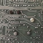
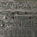
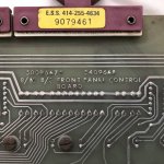
All I have here is a late 8/M 8/E panel so it also has screws on the back for the LED masks (steel with insulating washers) in addition to the larger mounting bar screws. On this board, the fasteners have been replaced with nylon screws but you can see how the traces are overlapped. A steel screw with washer would be about the same size. Likewise the smaller mask screws - they are very close the traces in a few spots and could lead to "interesting" issues.
IMG_1342u.jpg

IMG_1343u.jpg

IMG_1344u.jpg
 
I see the nylon standoffs from the metal lamp holder to the front panel board. There weren't any nuts on them so I totally missed that. Putting nylon nuts on there would make it a real pain in the butt to get the front panel out.with the metal bar attached.
.
 
What is the proper height for the metal lamp seperator? With the lamps completely enclosed by the metal bar or protruding out from it?
 
PICs for previous messages about my front panel.
 

Attachments

  • photo63526.jpg
    photo63526.jpg
    263.2 KB · Views: 3
  • photo63527.jpg
    photo63527.jpg
    236.9 KB · Views: 3
  • photo63528.jpg
    photo63528.jpg
    163.2 KB · Views: 3
  • photo63529.jpg
    photo63529.jpg
    127 KB · Views: 3
  • photo63530.jpg
    photo63530.jpg
    115.3 KB · Views: 3
Front panel and light bar should be bolted together as one rigid assembly. The whole thing goes into the front backplane slot and then the ends of the bar are screwed to the case ears. This will give you a lot more solidity when you flip the switches. Removal is the reverse - the whole assembly lifts out by unbolting the ends of the light bar from the case and then unplugging the front panel PCB. Once removed, the light bar is then unscrewed from the back.
 
All I have here is a late 8/M 8/E panel so it also has screws on the back for the LED masks (steel with insulating washers) in addition to the larger mounting bar screws. On this board, the fasteners have been replaced with nylon screws but you can see how the traces are overlapped.

That one is quite different than the ones I have here. I have a 5409057D and a 5409057J. I'm looking at the "J" at the moment, and the lights bar is held on with two largish nylon screws, one near the upper right, and the other about 1/3 in from the left. The latter is near the rotary switch, and also has a 1/4" or so nylon spacer under the screw head. The rotary switch has a couple of nylon nuts. In addition, there are four nylon screws holding the switch alignment bars. Each switch alignment rail has a screw on near the right edge and a screw near the left edge.

On mine, the back of the lights bar is at about the level of the front of the plastic bulb bases. The glass of the bulb is enclosed in the metal of the bar, allowing only light from that bulb out the front.

As Jack points out, several of these nylon screws overlap or border on traces.

Vince
 
Back
Top