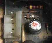
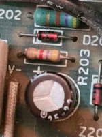
The resistor is a 4.7K, 1%, 0.5W
The capacitor is a 22uF, 25V electrolytic job
Capacitors can and do fail, but usually a semiconductor fails first (diode/MOSFET etc), and what you see is the resulting bloody aftermath.
These parts are available for cheap at digikey or mouser, but I fear replacing them will not fix your power supply.
-Alon.
View attachment 66993
The resistor damage is most certainly caused by something else acting up, while the capacitor might as well be the root cause. A dried out capacitor could cause all sorts of problems if it is located in the control circuitry. But it can just as well as you say be some other component that is the root cause.
In general from my experience there are a number of usual problems in switch mode PSUs.
1. Short-circuit semiconductor on the primary side. Usually blows the fuse immediately. Check all semis on the primary side for short circuit / or open circuit. Can be hard to do this test in circuit though since there can be transformer windings in parallell.
2. Short-circuit semiconductor on the secondary side. May blow fuse, but also may cause the supply to not start up due to over-current. A ticking sound may be heard. I also had other sound effects from supplies with shorted semis on the secondary side. Check all semis on the secondary side. Mostly there are rectifiers diodes.
3. Crowbar on the secondary side that trigger. Some time it can false trigger due to increased leakage in the SCRs. I have had increased leakage in one old SCR that caused strange problems. Or more likely the PSU is regulating badly which causes the crowbar trigger correctly. In this case I would temporarily remove the crowbar and investigate the feedback circuit in more detail. This can be done by feed the output from a bench supply.
4. Short-circuit filter caps. The same symptom as (2). Check the resistance on the outputs. It should not be zero ohms. Sometimes there is a resistor in parallell to create a minimum load for the supply. make sure to take this into account when measuring.
5. Bad caps in the control section of startup section. May cause bad regulation or problem to start the supply. I had a bad cap in the feedback loop which made the voltage to low on the outputs. It is good practice to check caps for capacitance and ESR.
6. Bad opto-couplers in the feed back loop. Some supplies use a opto-coupler between primary side and secondary side. For some reason these can go bad which cause regulation problems.
7. Bad inlet filter RIFA caps. They usually go off with a big bang and smoke. There is no real aftermath except for a very tedious cleaning of the circuitboard and perhaps replacing the fuse.
8. Bad high voltage 200VDC / 400VDC caps on the inlet. I have only seen these go bad once. But when they do they blow the fuses in my experience. Check the big high voltage caps for capacitance and ESR. Make sure to reform them slowly.
What I usually do when I get an unknown PSU that hasn't been run for long time is the following (at least a supply that cannot be easily replaced by something else. I would probably do this amount of work just for a stupid PC type supply) :
0. Check all semiconductors for shorts. Check caps in circuit for reasonable values. Check for burnt resistors and excessive heat generated that cause the board go dark.
1. Identify how to supply the control section from a bench supply. Sometimes there is a small AC mains transformer that give the startup voltage for the supply. In cheaper designs there is just a resistor divider from the input rectified AC. In any case I hook up my bench supply here and try to exercise the control circuit. Does it create a switching waveform to the chopper transistors? In many cases it will directly, but I have seen cases where the PSU measures the input AC voltage and refuse to do anything unless it is high enough. If that is the case I inhibited this circuitry to have the PSU to startup.
2. From another bench supply apply a voltage on the output that is regulated. It is usually the one with the highest current. 5V rail is very likely to be regulated. Now monitor the switching signal to the chopper transistors. As soon as one comes close to 5V (or whatever the rail that is regulated is), the waveform should start to shift and above 5V it should be a minimum pulse length. If this is ok, then the feedback system is probably not that bad.
3. I now use an isolating transformer that protects me from the mains in series with a variac. I connect the variac to the mains input of the PSU. With a scope I monitor the waveforms on the collector / drains of the chopper as I slowly crank up the input voltage, keeping the input at safe levels (below 50V or so) so I can poke around in the circuit with a scope probe. It can be useful to have some series resistance in case something goes really bad since then this will limit the current. Another option is to use a bench supply that can supply up to 50V or so. Is there voltages on the outputs? Without load it might be even that the supply starts regulating at very low input levels since the load is very little. The cranking up slowly part is also important since then the input caps will get used to high voltage slower. I have seen a case when a friend applied full voltage to a HP9845 directly and killed both the input caps.
4. When I am sure that the supply is regulating well and looks well-behaved at low AC levels in, I usually add a more appropriate dummy load. This all has to do with the rating of the supply. Perhaps something that would consume 5% of the rated current on the output that is regulated. With one hand in the pocket I continue to crank up the input voltage slowly monitoring the PSU for heat generation. A good HV differential probe can be used to check the waveforms on the drain / collector. Does it create the correct voltages on the outputs?
5. Remove the bench supply and increase dummy-loading and turn on the PSU directly. Continuously monitoring it for heat. Wearing safety glasses can be a good precaution. I have had tantalum caps explode at one occasion and it is not fun.
6. Put it all back together and run it for full load (if possible) for some time. Make sure that adequate cooling is provide, though.
There are some caveats. For example there might not be a proper schematic available. In that case it could be a good idea to sketch a schematic for important portions of the supply. Like the control section. Even worse is when the manufacturer (read IBM) put their very own markings on chips and other components. Then you need to do quite advanced reverse engineering to understand what is going on. I did this with the IBM 3279 supply which I managed to understand quite well and also made operating properly. BTW. It uses a standard TDA1060 control chip but marked with IBM secret codes...
On the other hand I still have a IBM 5110 PSU I am getting nowhere with since it has a bunch of square metallic boxes which I have absolutely no clue what they are doing.


