• Please review our updated Terms and Rules here

Memory test error with Toshiba T1100

Vint

Experienced Member
Joined
May 14, 2008
Messages
390
Location
Ohio, USA
My trusty Toshiba T1100 is showing it's age.
I only fire up this machine every few months but just the other day it did the following:
Upon booting (with a DOS 3.3 disk in A: drive) - the T1100 starts it's memory test. At 448K it gives 1 long beep and shows ERROR 700D6:0A and sits there. I then press RETURN and it gives 1 short beep and then boots fine from A: drive.

I think I have a RAM problem.
I opened the case (incidentally it's clean as a whistle inside.) I look around inside for some chips to reseat but most every chip is soldered down. I reseat what I can and buttoned it back up.

attachment.php


I get the same boot ERROR every time now. It used to finish nicely at 640K and boot DOS.

So, - I took the T1100 apart again. I pushed and prodded things and nothing helps. I believe when I make the effort to fix this thing, then it should cooperate, but it won't.

Any suggestions, my fellow vintagians?
 
Sounds like a DRAM failure. You can see by examining and playing with the locations around 700D:6 using DEBUG.

Try the following DEBUG commands:

F700D:0L10 FF
D700D:0L10

(you should see nothing but FF)
F700D:0L10 00
D700:0L10

(you should see nothing but 00)

If you get anything else, you've got a bad chip (or two). You can rework the board, but it's not something for a first-timer.
 
Thanks Chuck(G)

I ran DEBUG with the locations you gave me and they produce the word Error in every instance.Then I was digging around and found the original floppy disks and ran the Diagnostics on those.It says I have 448 K.It seems odd that 192 K got 'knocked' out but that's what happened. It's over my head here, but 192 seems an odd number. Why not 128 or something like that? I don't know how the DRAM chips divide up, but 192 K seems odd to me. (But I'm lost here anyway.) Don't guess I'll be correcting this problem, so I'll have to muddle along with 448 K as long as that holds up.

Darn, and the thing is only about 25 years old! Can't they make computers to last anymore? :eek:
 
Last edited:
Here's a DEBUG transcript of me doing exactly what I said above. Note that DEBUG produces a "-" prompt. Spaces do matter.
Code:
D:\>debug
-F700D:0L10 FF
-D700D:0L10
700D:0000  FF FF FF FF FF FF FF FF-FF FF FF FF FF FF FF FF   ................
-F700D:0L10 00
-D700D:0L10
700D:0000  00 00 00 00 00 00 00 00-00 00 00 00 00 00 00 00   ................
-Q

D:\>
 
Thanks Chuck(G)

...It seems odd that 192 K got 'knocked' out but that's what happened. It's over my head here, but 192 seems an odd number. Why not 128 or something like that? I don't know how the DRAM chips divide up, but 192 K seems odd to me. ...
192=128+64, so yeah it is 128 x 1 1/2 ;-)
 
I'm catching on now

I'm catching on now

Thanks again for walking me thru this Chuck(G)

As you can tell I'm not a Debug whiz. Now that I've keyed in correctly per your example I have the following -

attachment.php


So, if that works correctly, I wonder what's producing this error?

attachment.php


Also, by MikeS tally - I now see where the 192 comes from - Thanks :satisfie:
 
Thanks again for walking me thru this Chuck(G)

As you can tell I'm not a Debug whiz. Now that I've keyed in correctly per your example I have the following -

attachment.php

If you look carefully, the "FF FF FF..." row about halfway through starts displaying "F0 F0 F0...". That looks like to me where the memory is bad. If I'm not mistaken (please correct me if I'm wrong), the debug test is writing all 1s to all of the addresses in the RAM and reading them back, then writing all 0s and reading them back. So it looks to me as though you only have about 3/4ths of your RAM operational.

Kyle
 
Yup, the "F0" tells all. Most likely, you've got a failed DRAM chip. Since I don't know what kind of DRAM your system uses, it's hard to figure which DRAM chip it might be. But you wrote 1's in the lower 4 bits of each byte and more than half of them came back 0's.

And the error starts at--are you ready for this?--physical address 700D6.

There you go...

Why doesn't it use the other hex characters to show exactly which bits aren't being displayed? You say that if more than half of them come back as 0s, it shows a 0.

I guess I'm just used to the memory debugger my SWTPC uses!

Kyle
 
Why doesn't it use the other hex characters to show exactly which bits aren't being displayed? You say that if more than half of them come back as 0s, it shows a 0.

I guess I'm just used to the memory debugger my SWTPC uses!

No, I didn't say that. I said: "But you wrote 1's in the lower 4 bits of each byte and more than half of them came back 0's."

In other words, you wrote 16 bytes with all bits set to "1". Over half of those 16 bytes (10 to be exact) did not show values with the lower 4 bits set to "1".

Merely stating the obvious...
 
DRAM chips are TMM41464P-15

DRAM chips are TMM41464P-15

I think I've stumbled across the RAM chips.

attachment.php


I think it's cruel of Toshiba to solder them down. It's not like they were going to fall out with all them legs. Anyway I haven't tried unsoldering IC chips since the 70's (if that tells you anything.) I think I might give it a go though - if the chips are cheap. I'll poke around some more but just a few brief Googles didn't produce a cost.
Question: If I were to take a good TMM41464P-15 chip and piggyback it over each of the 8 DRAM chips - would that procedure cull out the bad ones? Guess I'd have to boot with each chip test to see if the RAM test changed from 448K each time - but that sounds easier than unsoldering all 8 chips and replacing them.
Normally I wouldn't do this sort of thing, I'd just go look for another machine - but I'm inspired by TEZZA, and his stories of success poking around inside the vintage gear :cool:
 
I don't think that isolating the faulty chip will be difficult. These are 64Kx4 bit chips (accounts for why 4 bits of each byte get knocked out).

It's nice that the IC numbers are silk-screened on the PCB. I'd imagine that the designers assigned RAM chips in pairs and that each pair is 64K bytes. So do your arithmetic and figure out which pair it must be.

Can you piggyback replacements? Maybe, but I'd isolate pin 1 (output enable) of the bad (under chip of the piggyback) from the PCB and the piggyback just in case. Since this is a laptop, you'll want to eventually replace the bad chip to keep power consumption down.
 
No, I didn't say that. I said: "But you wrote 1's in the lower 4 bits of each byte and more than half of them came back 0's."

In other words, you wrote 16 bytes with all bits set to "1". Over half of those 16 bytes (10 to be exact) did not show values with the lower 4 bits set to "1".

Merely stating the obvious...

Ahh, it got me confused! :) I see now...that makes a lot more sense! Hex still is a bit confusing to me, but I think I got it now.

Unsoldering DIPs are no fun...I wanted to rescue some 74141s (Nixie driver) in a broken time code generator, but after I chipped part of one, I just gave up. Plus, the whole board was sprayed with some lacquer, which only added to the pain of removing the chips! Good luck, though!

They do make a fancy DIP chip tip (like the rhyme? :D) for a soldering iron. I haven't personally tried one, but it sure would make removing the chip a lot easier, since it heats all of the pins at once.

Kyle
 
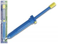
Get yourself a temperature-controlled soldering iron (if you don't have one) and one of these:

solder_sucker_vtd2.jpg

Get the big one, not the cute little metal ones. eBay's got them all over the place; just search for "desoldering". You can also get them for about the same price from Marlin Jones.

With a little practice, you'll get a nice clean job. Just wiggle the IC a bit and it'll come right out of the board.
 
I have a T1100 (not a T1100 PLUS). In the T1100, Toshiba supplied 256KB RAM on the mainboard with an optional extra 256KB provided on a small plug-in board (right about where that small vertical board is in the right of your last photo).

But you've indicated 640KB total RAM, so I figure that you have the T1100 PLUS, not the T1100.

Those eight TMM41464P chips in the picture add up to 256KB (eight times 64Kx4 bit), and so the physical memory layout in the T1100 PLUS must be similar to the T1100. That means that the RAM failure is in the small removable vertical board (assuming that in the T1100 PLUS, that board is the extra RAM).

Assuming that all of that is correct, then one option you have is to take the T1100 PLUS back to a 256KB only configuration. At least it will boot. That would involve removing the vertical board and setting switches SW2 and SW3 to the ON position (per the switch table at http://www.toshiba.pcxt-micro.com/detail/t1100p.txt ).

That document also indicates that the optional 384KB board is part number PA7132U. Obviously if you find "PA7132U" on that vertical board, that verifies the above.
 
Modem7, good observation on the DRAM.

If the added memory is SMT on the add-on board, it still can be repaired--it's a little more tricky, but still doable. To remove SMT packages, I use Chip Quik or a clone thereof. Low temperature with no danger of damaging the PCB and very localized action.
 
Viola!

Viola!

Well modem7 you've done hit the nail on the head!

Look at this -

attachment.php


I followed your guide and now my Toshiba happily boots up with it's paltry 256K, but running smooth. Thank you :) Here's the board in place.

attachment.php


You know my first gut reaction when I opened the machine originally - is that that board was RAM, but I got sidetracked and through not 'paying attention' and thinking it all through of just what I was doing. - I mean I made several foolish mistakes. Like, I was thinking those 8 DRAM chips soldered on the main board was the whole 640K of RAM. Now I realize that even if I was thinking 8 chips x 64k that would only be 512k - Duh, on me. Then I'd have gone looking for more RAM and stumbled over the vertical board.


The switch over -

attachment.php


And the resulting 256K completes the repair as this diagnostic test shows.

attachment.php


I requested a price for a listed 'refurbished' PA7132U 384k expansion board from a company I Googled. I would like to return my T1100 PLUS back to it's original state if it's cheap enough.

I do remember back yonder in years of using one of those solder suckers I bought at Radio Shack. I probably still have it out in the garage somewhere. Also I remember using solder wick to desolder things quite easily and neatly.

This thread has been quite fun and informative for me, guys - Thanks - one and all :)

- - Note: I removed the board PA7132U bringing the RAM down to 256K.
 
Last edited:
Back
Top