mikerofone
Experienced Member
Hi all,
TL;DR:
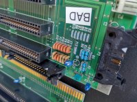
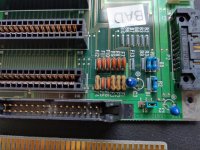
I need to identify a fault in a connector board that seems to only house connector headers and passive components: capacitors, resistors and some mystery things I need help identifying. What are the things marked "F1" through "F12" on the silkscreen? I'd have guessed fuses, but they have three pins. The outer ones measure as direct shorts, and to the middle pin they both measure as open lines.


The long story
I've got two NEC PowerMate Portable Plus units recently (not much information online, but there's this). After recapping the power supplies, which both had very very failed caps (there was a puddle of electrolyte in the PSU housing) they both worked fine for a couple hours.
Then after turning one on after a few weeks of it being stored in my apartment, it started fine for about 5-10 seconds but then made a somewhat wet, smoochy sound (really hard to describe) that wasn't the usual crackle/sparkle that I'd associate with a blowing tantalum capacitor. You could see that there was a short power drop (HD spun down and back up, backlight flickered) and I shut the machine off. I found some liquid in the PSU that was stuck in the fan header. Not sure where it came from (I didn't wash the boards, so maybe more electrolyte was hidden under components that managed to flow into there. I cleaned it out, and the PSU works again. But now the internal screen no longer shows an image, even though the backlight turns on and there is an image on the VGA output.
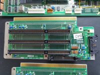
Aside from the screen, the machine is working fine again. I started swapping parts between the working and broken machines and verified the screen and mainboards both to be working. There is one connector board that sits between the screen and the mainboard, and houses the ISA ports as well as the connector for the front panel contrast/brightness knobs (see first image). I've isolated the fault to this board: If I use the one form the bad machine in any screen / mainboard combination, the internal screen illuminates but stays blank. Swapping for the good one makes any combination work well.
The top edge connector plugs into the mainboard, the screen into the connector on the opposite end with a ground wire screwed to the ground hole next to the connector. On the right, the front panel with the contrast/brightness controls connect.
I've verified the capacitors with an ESR/Capacitance tester and they check out good and with close to identical values on both boards. So I guess maybe these "F" components might be bad, but I don't know what they are or how to test them. The "B" ones seem to be simple wires ("bridge"?). Any suggestions?
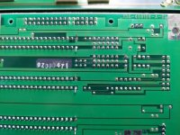
I'll start beeping out traces to compare the good vs bad board, but I don't see any damages with the naked eye there. Hints as to where to go next are welcome!
Thanks for reading!
mikerofone
TL;DR:
I need to identify a fault in a connector board that seems to only house connector headers and passive components: capacitors, resistors and some mystery things I need help identifying. What are the things marked "F1" through "F12" on the silkscreen? I'd have guessed fuses, but they have three pins. The outer ones measure as direct shorts, and to the middle pin they both measure as open lines.


The long story
I've got two NEC PowerMate Portable Plus units recently (not much information online, but there's this). After recapping the power supplies, which both had very very failed caps (there was a puddle of electrolyte in the PSU housing) they both worked fine for a couple hours.
Then after turning one on after a few weeks of it being stored in my apartment, it started fine for about 5-10 seconds but then made a somewhat wet, smoochy sound (really hard to describe) that wasn't the usual crackle/sparkle that I'd associate with a blowing tantalum capacitor. You could see that there was a short power drop (HD spun down and back up, backlight flickered) and I shut the machine off. I found some liquid in the PSU that was stuck in the fan header. Not sure where it came from (I didn't wash the boards, so maybe more electrolyte was hidden under components that managed to flow into there. I cleaned it out, and the PSU works again. But now the internal screen no longer shows an image, even though the backlight turns on and there is an image on the VGA output.
Aside from the screen, the machine is working fine again. I started swapping parts between the working and broken machines and verified the screen and mainboards both to be working. There is one connector board that sits between the screen and the mainboard, and houses the ISA ports as well as the connector for the front panel contrast/brightness knobs (see first image). I've isolated the fault to this board: If I use the one form the bad machine in any screen / mainboard combination, the internal screen illuminates but stays blank. Swapping for the good one makes any combination work well.
The top edge connector plugs into the mainboard, the screen into the connector on the opposite end with a ground wire screwed to the ground hole next to the connector. On the right, the front panel with the contrast/brightness controls connect.
I've verified the capacitors with an ESR/Capacitance tester and they check out good and with close to identical values on both boards. So I guess maybe these "F" components might be bad, but I don't know what they are or how to test them. The "B" ones seem to be simple wires ("bridge"?). Any suggestions?
I'll start beeping out traces to compare the good vs bad board, but I don't see any damages with the naked eye there. Hints as to where to go next are welcome!
Thanks for reading!
mikerofone
