• Please review our updated Terms and Rules here

Macintosh SE/30 - CRT Ghosting / Bleeding?

smiba

Member
Joined
Aug 29, 2020
Messages
11
(Originally posted this on 68kmla but got recommended to post it over here by a friend of mine, hopefully any of you can help me out!)

I've recently bought a troubled Macintosh SE/30 for way too much money.
(Issues with HDD, FDD, motherboard with extremely leaky battery and now also the CRT lol....)

I'm still working on some of the issues and waiting on replacement capacitors, the ugliest ones have been replaced but with the audio being extremely faint too I think all of them are in dire need.

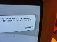
Anyways, I'm making this topic to get some feedback on how to resolve this issue with the CRT. The image seems to "ghost" or affect the image to the right, its not extremely heavy but its enough to kinda bother me.
The alignment and geometry of it is mint, extremely pleasing to look at.
qEYiFpB.jpg

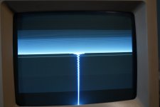
Not sure if this is related, but pressing the reset button very clearly shows the horizontal sync collapsing, resulting in a "lightning strike"
hhFymvX.jpg

Analog board looks good from a glance, but I haven't removed it as the internet made me afraid to work on high voltage stuff like CRTs :p
 
Compact macs are notorious for problems on the analog board/power board. The smearing and H/V collapse could be a result of bad solder joints and/or bad capacitors. You'll want to touch up all of the solder joints if you can't see any that obviously look bad. Hairline cracks in joints are hard to see without magnification most of the time. You'll also want to reflow the joints on the neck board/connector on the CRT as well because those also fail.

And you'll definitely want to discharge the tube manually before working on the machine, never trust the bleeder resistors, especially when there's a fault. The easy way to do it is get a good flat blade screwdriver with an insulated handle, attach a wire firmly to the shank, a 1W 1 megohm resistor to the wire, and another wire to the other end of the resistor to the metal CRT mount on the front of the chassis. With the unit off AND unplugged, poke the screwdriver under the anode cap on the side of the CRT and touch the anode wire. You may or may not hear a pop from it arcing to the screwdriver, hold it there for several seconds and the tube should be safe until you plug the machine back in.

When working on CRTs, it's always important to have a healthy amount of fear, because when you don't, you start making mistakes and get hurt.
 
Thanks!

Makes sense, I'll work on the analog board after I've finished the recap of the mainboard. I'll check the traces on the mainboard related to video signal too, just to be sure.
I'll let you know when I have an update!
 
Recap of the mainboard resolved some other issues like the audio and the device not resetting properly but the screen related issues are still there.

I checked R20/21/22 on the motherboard as those are on the video path but they all came back with no more then 0.5% out of specification. C40 looked cosmetically great, didn't measure it in particular as I didn't want to disturb it unnecessarily.

Any resources on recapping the analog board you'd recommend? I'd love to possibly replace some of the parts on the video signal path too
 
Recap of the mainboard resolved some other issues like the audio and the device not resetting properly but the screen related issues are still there.

You'll need to recap the analog board if you haven't already.

C40 looked cosmetically great, didn't measure it in particular as I didn't want to disturb it unnecessarily.

Capacitors can fail without showing visual symptoms like bulging or leaking. Old caps especially can dry out from the rubber plug on the bottom dry rotting/shrinking and letting air in. This can make them go open, short, have high ESR or out of spec capacitance.

Any resources on recapping the analog board you'd recommend? I'd love to possibly replace some of the parts on the video signal path too

Diagnostic and repair information for older CRT televisions is a place to start, it will give you at least an idea where things can go wrong, why and how to fix them.

If you replace the capacitors, make sure you get the proper rated caps. Some analog boards require special capacitors, like non-polarized electrolytics and/or high frequency rated caps. If you use a normal general purpose cap in the wrong place, it can cause damage if the circuit doesn't have protection.
 
Replaced all caps except for the 3.9uF/35V bipolar which I didn't have a replacement for. Considered making a replacement with 2x 10uF regular caps, but with 5uF that would've been more then 20% out of spec.

All the caps that I removed measured above their rated capacitance (except for the 1000uF, which came back as 950uF) and their ESR all were within reasonable values.
I'm even keeping the 4400uF in my capacitor stash as that one reads as 5100uF with a <0.05Ohm ESR, pretty good stuff for something with a datecode from 1991.

Problems are still there with the horizontal signal collapsing weirdly on reset (although not an issue when running, so I really don't care) and the ghosting (which I really DO care about).
Wonder if I should still replace the 3.9uF bipolar, it goes to the yoke before the width adjustment so it is related to the horizontal sweep... (but not data)

I'm probably gonna swap the CRT Board (little board that goes onto the tube) with another Macintosh SE/30 I'm working on. It should work, but I haven't extensively tested it, lets see if that resolves the issue maybe...
If this is a problem with the tube itself, what causes this?
 
Replaced all caps except for the 3.9uF/35V bipolar which I didn't have a replacement for. Considered making a replacement with 2x 10uF regular caps, but with 5uF that would've been more then 20% out of spec.

The 3.9uF capacitor is a special high frequency rated capacitor for horizontal sweep, it MUST be replaced with the same type. Subbing it out with a general purpose capacitor, or fudging it with two back to back capacitors will most likely cause something to forcibly detonate. There's a reason that the capacitor is so large. Unfortunately, such capacitors are becoming rare because modern digital electronics doesn't really have a need for a HF deflection capacitor. I've seen a few people have trouble finding a suitable replacement.

All the caps that I removed measured above their rated capacitance (except for the 1000uF, which came back as 950uF) and their ESR all were within reasonable values.
I'm even keeping the 4400uF in my capacitor stash as that one reads as 5100uF with a <0.05Ohm ESR, pretty good stuff for something with a datecode from 1991.

Capacitor tolerances are usually +/-20% for electrolytics. If the capacitor rates too high, there's a good chance it's electrically leaky. The paper inside the capacitor eventually goes acidic and causes the capacitor to pass DC current, which is bad. Testing electrically leaky caps usually show much higher than rated capacitances because the capacitor is draining the charge as it's being tested, which confuses the tester.

I'm probably gonna swap the CRT Board (little board that goes onto the tube) with another Macintosh SE/30 I'm working on. It should work, but I haven't extensively tested it, lets see if that resolves the issue maybe...
If this is a problem with the tube itself, what causes this?

I'm going to guess that there is a bad or marginal component somewhere on the analog board causing the collapsing issue and the smearing. There's no failure mode of the cathode ray tube itself that would cause smearing/ghosting unless the screen was burned in.

If you decide to swap analog boards, BE SURE that the CRT from the donor machine is of the same type or something is going to die.
 
The 3.9uF capacitor is a special high frequency rated capacitor for horizontal sweep, it MUST be replaced with the same type. Subbing it out with a general purpose capacitor, or fudging it with two back to back capacitors will most likely cause something to forcibly detonate. There's a reason that the capacitor is so large. Unfortunately, such capacitors are becoming rare because modern digital electronics doesn't really have a need for a HF deflection capacitor. I've seen a few people have trouble finding a suitable replacement.

I've seen people replace it with a film cap, any idea if that would be suitable?
What would its tolerance be in this circuit? Would I be able to use a very slightly more common 4.7uF?

board.png

Capacitor tolerances are usually +/-20% for electrolytics. If the capacitor rates too high, there's a good chance it's electrically leaky. The paper inside the capacitor eventually goes acidic and causes the capacitor to pass DC current, which is bad. Testing electrically leaky caps usually show much higher than rated capacitances because the capacitor is draining the charge as it's being tested, which confuses the tester.

I didn't know, TIL!


I'm going to guess that there is a bad or marginal component somewhere on the analog board causing the collapsing issue and the smearing. There's no failure mode of the cathode ray tube itself that would cause smearing/ghosting unless the screen was burned in.

If you decide to swap analog boards, BE SURE that the CRT from the donor machine is of the same type or something is going to die.

I mean if you really want to I could just swap out the other components (except ICs and flyback) too... but it will be a pain in the ass. (Also its just guessing at that point..)

The CRT is the same type, all Macintosh SE's have the same video board. I have my doubts the CRT board will have any impact, its pretty much passive with components that barely degrade (ceramic caps, resistors).
There is a transistor on their which processes the data signal though. I don't see transistors just wear out usually, but its probably the only thing on the board that does.

board2.png
 
Swapped the CRT board and its behaviour is exactly the same sadly
I'll probably just swap the CRT next just to rule out the tube, I fear for the results though. (I think its the tube)

(To the mods, feel free to combine this post with my other still pending response when approving)
 
Did a CRT swap and this solved the issue
So its either in the tube or the wires going to the yoke (Signal wires for data are going to the PCB Board, which as shown didn't change its behaviour)

Any idea what might cause an CRT to behave like this? Is there a remedy?
 
I've seen people replace it with a film cap, any idea if that would be suitable?
What would its tolerance be in this circuit? Would I be able to use a very slightly more common 4.7uF?

I'm not experienced enough with analog circuitry to say whether subbing a polypropylene capacitor will work or not. I'd look at the datasheet for the 3.9uF capacitor and try to get something as close to it as possible in regards to how high its frequency rating is.

I mean if you really want to I could just swap out the other components (except ICs and flyback) too... but it will be a pain in the ass. (Also its just guessing at that point..)

Shotgun replacing components is indeed never a great idea, but with limited analog circuitry experience and no specialized test equipment like an oscilloscope, it makes it hard to diagnose faults.

its pretty much passive with components that barely degrade (ceramic caps, resistors).There is a transistor on their which processes the data signal though. I don't see transistors just wear out usually, but its probably the only thing on the board that does.

Transistors, resistors and ceramic capacitors can fail just like electrolytic capacitors can. Electrolytic capacitors going bad can actually cause other components to fail. When they start passing DC current, it can drive circuitry both before and behind it very hard and cause components to blow up or fry. I see it happen all the time in switchmode power supplies.

Resistors are the worst when they fail, because they can drift in value, go completely short or blow open internally and look perfectly fine visually. Ceramic capacitors can crack, which can short or open the layers. Transistors can also short between the EBC/GDS in any number of ways.
 
Just replaced the tube and the replacement tube doesn't show any issue.
Same internals everything, same PCB Board too.

I don't really understand how a CRT can fault in a way where it smears like this, any clue where to look?
 
B&W tubes are very simple, they have no shadow mask or aperture grille, it's basically the cathode gun, screen phosphor and the anode return cap.

The only three things I can think of are that there's some issue on the yoke, there's a short or other problem in the cathode gun, or the tube has partially outgassed.

The X and Y windings on the yoke should be checked for both inductance and resistance, then compared to a good tube to see if the values are off. I remember reading about another compact mac tube where one of the windings had shorted and had like half the inductance it should have and caused strange picture issues. You can rewind a yoke, it's just a PITA because of the precision required when winding. You'll also probably have to faff with the tuning magnets on the yoke since the magnetic field would be slightly different in the case of a rewinding.

If there's a problem with the cathode gun, there's not much you can do. There used to be CRT Rejuvination machines that could burn clear faults in the cathode gun, but these are very difficult to find, and even more difficult to find in working order. They're also dangerous to use since they're often not isolated from the mains, and have B+ voltage in the 300-500v range. Adrian Black on Youtube that run's the "Adrians Digital Basement" channel has one of these machines, maybe you can work out a deal for him to use his rejuvinator on your tube.

And finally, if the tube has started leaking, there's really nothing you can do. You can check if the tube has started to leak if the getter compound in the neck of the tube, which is usually a silver stain on the glass has either started to disappear, has already disappeared, or is starting to turn white from oxidation. I don't think this is likely though, because symptoms of a gassy tube are usually arcing in the cathode gun, or a blue glow in the tube.
 
I'll check the resistance of the yoke compared to the one that works correctly.
I don't have an easy way to check inductance

The yoke most likely is fine though, as the entire thing is caked in glue and looks to be in good condition (visually)

The tube has had a good runtime on it most likely, as it was part of an office building and then has had many years as a machine primarily used for writing.
I'd be more then happy to buy a CRT Rejuvinator, there is a B&K 470 available for sale for €150. (~$180) A bit expensive (considering I can also buy a second hand replacement CRT for this machine for €50) but it may come in handy in the future.

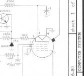
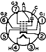
Just to be sure if I do so, is the CR-7 adapter correct? Their manual specifies that the CR-7 adapter is used for "miniature special B&W Types (Like B+K 12CWP4)", the size and pin-count seem to match. I'm slightly unsure about some pins, as they point to different places in the raster... but I'm not sure how to read the image.

Do you have any clue if these two are matching?

(My CRT vs. 12CWP4 CRT)
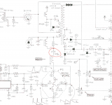
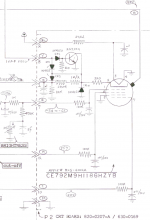
schematic_tube.PNG tube_socket.png

The only difference seems to be pin 5, which doesn't share the same location on the raster as pin 1. (As it does on the 12CWP4's socket) But this may just be schematic limitation... Again not sure if the location on the raster indicates anything specific


(Sources, https://www.arcade-museum.com/manuals-monitors/BK detailed adapters.pdf & https://www.radiomuseum.org/tubes/tube_12cwp4.html )
 
Last edited:
I'll check the resistance of the yoke compared to the one that works correctly.
I don't have an easy way to check inductance

Might want to invest in an LCR meter. Those cheap chineseium capacitance testers can test for inductance (usually), but you'd probably want to check a known good inductor with its listed value to see if it's calibrated properly.

The yoke most likely is fine though, as the entire thing is caked in glue and looks to be in good condition (visually)

Is it that horrible hard yellow glue? That stuff is both corrosive and becomes conductive over time, which can cause havoc. I've had to spend hours chipping that stuff out of power supplies that it has caused to short out. I had one PSU where the manufacturer had splurged the glue all over several inductors, and the base of switching transformers. It had eaten into the copper windings and required the inductors to be replaced and transformer base to be repaired.

Try poking the glue with your multimeter in ohms mode in several places. If you see anything being registered, then the glue has become conductive, and is most likely eating into the copper windings.

Just to be sure if I do so, is the CR-7 adapter correct? Their manual specifies that the CR-7 adapter is used for "miniature special B&W Types (Like B+K 12CWP4)", the size and pin-count seem to match. I'm slightly unsure about some pins, as they point to different places in the raster... but I'm not sure how to read the image.

Do you have any clue if these two are matching?

(My CRT vs. 12CWP4 CRT)
View attachment 63345 View attachment 63346

The only difference seems to be pin 5, which doesn't share the same location on the raster as pin 1. (As it does on the 12CWP4's socket) But this may just be schematic limitation... Again not sure if the location on the raster indicates anything specific

I've never used a rejuvination machine myself, and tube technology is far out of my area of expertise to give you proper advice. I'd suggest doing lots of research, and maybe finding an old radio community which knows about vacuum tubes. Mr. Carlson's Lab on YT has a bunch of stuff on old vacuum tube gear, as well as a Patreon where you can ask questions and have them answered.
 
Back
Top