• Please review our updated Terms and Rules here

Need help with RTC battery Compaq Deskpro 386/20e? model 000935-001

k2j

New Member
Joined
Jul 5, 2019
Messages
9
Hi guys/gals,

I discovered this old motherboard at my place of employment almost exactly 20 years ago. Ever since then it has donned a special place on or near my desk. Well, now having basically started working from home and lots more spare time than before I decided to bring it with me and revive it!

I've searched high and low for more specifics on this motherboard, but not having much luck. The closest I found is 001906, but it is slightly different than that board.

So, I have been able to get it to boot and the setup program works too, but without the battery of course it won't save this info.
On the PCB there are 2 distinguished plugs and I assume that one must be for an external RTC battery.
I am guessing that it is going to be the U66 that consists of 3 pins (2, space, 1)? And maybe the other plug near the PS2 ports is for a fan?
Can someone verify that is the case and if so what the pinouts are for them?
Also curious if someone has a photo or copy of the 2 dipswitch settings?

thanks for any help!! I'm really excited to breath life back into this sentimental relic.
 

Attachments

  • photo63127.jpg
    photo63127.jpg
    164.4 KB · Views: 4
  • photo63128.jpg
    photo63128.jpg
    162.2 KB · Views: 5
  • photo63129.jpg
    photo63129.jpg
    154.1 KB · Views: 4
  • photo63130.jpg
    photo63130.jpg
    166.1 KB · Views: 4
Thanks!

Am I good with stacking a couple 2032's in a holder? Also, does this require a chargable battery or a diode to block charging current? Do I need to tie the 2 adjacent pins to ground or does just connecting say the outer of the 2 pins suffice?

cheers!
 
Almost always, the external connector is for a primary battery, not a rechargeable one--I don't think your board is any different. A couple of coin cell 2032s would probably be just fine.
 
SW1 Switch Settings
System Board (000935, 001196, and 001316)

1 ON* Enable fail-safe
1 OFF Disable fail-safe
2 OFF* 387 coprocessor not installed/Weitek installed
2 ON 387 coprocessor installed
3 OFF* Enable memory caching in 12MB - 16MB range
3 ON Disable memory caching in 12MB - 16MB range
4 OFF* CPU boot speed 20MHz
4 ON CPU boot speed 20MHz except 8MHz when accessing diskette drive
5 OFF Reserved
6 ON* EGA, RGBI, or VGC
6 OFF Third-party monochrome (MDA only)
7 8 ON* ON* 640KB base memory
7 8 OF OFF 256KB base memory
7 8 ON OFF 512KB base memory
OFF ON Reserved
* Default.

SW2 Switch Settings
System Board (000935, 001196, and 001316)

1 OFF* Primary diskette and hard drive address select (3FX & 1FX)
1 ON Secondary diskette and hard drive address select (37X & 17X)
2 OFF* Enable power-on password
2 ON Disable power-on password
3 OFF* Enable integrated hard drive controller
3 ON Disable integrated hard drive controller
4 5 OFF* OFF* Serial interface COM1 IRQ4
4 5 ON OFF Serial interface COM2 IRQ3
4 5 ON ON Disable serial interface
4 5 OFF ON Reserved
6 7 ON* OFF* Select printer interface LPT1 (3BX)
6 7 OFF ON Select printer interface LPT2 (37X)
6 7 ON ON Disable printer interface
6 7 OFF OFF Reserved
8 OFF* Enable integrated VGC
8 ON Disable integrated VGC
* Default.

Jumper Setting Function
E4 2-3* Enable pointing device interface
E4 1-2 Enable IRQ12 from bus, disable pointing device
E10 1-2* 8-bit video ROM
E10 2-3 16-bit video ROM

If it helps, the Compaq Spares part number for the battery is 112654-001 (for System Boards 001196, 001316 and 000935).
 
The specs on the 112654-001 are 3.6V. So I have used just 1 CR2032 measuring 3.3V. Should suffice. But I cannot get it to save the data. I have tried the negative connected to both together and each individually of the 2 adjacent pins (just below U66&U81 and no change. Any chance someone might know where I'm going wrong? could it be backwards?
Thanks -
 
On these external connectors, you have to understand that there are a few bandgap drops before it gets to the chip. My customary supply when using external battery connectors is to use 4.5 or 6 volts (e.g. 4xAA alkaline cells). I've been doing that for years.

You can check polarity with a simple continuity check. the 2 pins that should be negative will be the same as ground anywhere else on the board. Check that.
 
Good to know, I have a Deskpro XE450, and I had two AA's on the external battery connector. It caused all sorts of weird issues. It would forget the settings every boot, and most of the time wouldn't boot from the IDE disk. I eventually put a new lithium cell on the motherboard, and all is well. Think my issues could have been just from low voltage?
 
Consider that the PC AT with no charging circuit takes a 6V lithium battery. See this MZD bit on the 5170 battery

I've had quite a number of 386/486 motherboards with only an external battery connector. It's always been 4xAA (6V) that does the job--a set of alkaline batteries can last a decade. No need to get fancy--just make sure that they're securely away from the PCB in case of leakage--I put mine in a small plastic bag. If they leak, it's the cheap battery holder that gets ruined, not the motherboard.
 
I use lithium primary AAs myself. Will last a bit longer than alkaline and pretty much never leak. They also have a slightly higher open circuit voltage, so you can get away with only needing 3 of them
 
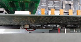
Well, as luck (or divine intervention?) would have it. I stumbled upon the exact model computer 386\20e.

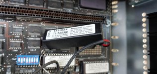
I still can't believe my luck, but thought I would post a few pictures of clarification in case someone stumbles on this thread in the future.

The battery actually plugs into the 2 adjacent pins and not at all to the single pin, with positive to the inside.

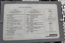
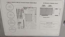
Also have included the Dip Switch settings for this specific board (000936-001 or 000935-001) since it is a bit different.

battery plug.jpg
switch settings.jpg jumper and switch locations.jpg battery.jpg
 

Attachments

  • jumper and switch locations.jpg
    jumper and switch locations.jpg
    199.5 KB · Views: 3
  • jumper and switch locations.jpg
    jumper and switch locations.jpg
    199.5 KB · Views: 2
  • jumper and switch locations.jpg
    jumper and switch locations.jpg
    199.5 KB · Views: 2
  • jumper and switch locations.jpg
    jumper and switch locations.jpg
    199.5 KB · Views: 2
  • battery plug.jpg
    battery plug.jpg
    139.8 KB · Views: 4
  • jumper and switch locations.jpg
    jumper and switch locations.jpg
    199.5 KB · Views: 1
  • switch settings.jpg
    switch settings.jpg
    148 KB · Views: 1
  • battery.jpg
    battery.jpg
    159.4 KB · Views: 3
  • battery.jpg
    battery.jpg
    159.4 KB · Views: 2
  • switch settings.jpg
    switch settings.jpg
    148 KB · Views: 4
Yes, no kidding I can't seem to find where that pin goes!

This thing is a real bugger, I'm currently fighting an Xtide bios on a NIC with CF (which I have done successfully on at least a dozen older PC's) and so far it has been very hit and miss.

Its so strange how the 'Winchester' cable is reversed between the controller and the drive. Going to be a long battle! Its almost like the Fixed disk controller doesn't completely disable. weirdness.
 
Back
Top