Upcoming Events:
- VCF South West - June 14 - 16, Davidson-Gundy Alumni Center at University of Texas at Dallas
- VCF West - Aug 2 - 3, Computer History Museum, Mountain View, CA
- VCF Midwest - Sept 7 - 8 2024, Schaumburg, IL
- VCF SoCal - Mid February 2025, Location TBD, Southern CA
- VCF East - April 2025, Infoage Museum, Wall NJ
-
Please review our updated Terms and Rules here
You are using an out of date browser. It may not display this or other websites correctly.
You should upgrade or use an alternative browser.
You should upgrade or use an alternative browser.
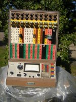
I now have an Analog Computer - EAI PACE TR-10
- Thread starter g4ugm
- Start date
g4ugm
Veteran Member
OK well its time to power it on. I removed the PSU and ran it on a VARIAC for 30 minutes to re-form the caps. Its only low voltage so this should be OK. Checked PSU rails on my scope and only a couple of Millivolts of ripple. Ramped it up to full voltage and installed in the machine. Powered the whole thing on and there were no sparks or bangs so that sounds good.
I patched all the op-amps to have unity gain but sadly most of them just flip off to infinity so I am going to have to start de-bugging them. There is a TR-20 Maintenance Manual on the web so I downloaded that. It looks like the circuits for the Amplifiers are almost the same as those for the TR-10. Just the TR-20 has the input resistors on the amplifier boards, where with mine you are supposed to have separate ones which go in-line with the leads....
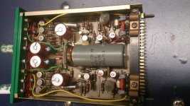
Actually the jumper plugs seem to have some kind of think white powder on them,. Not sure if this has leached from the plastic, any one any thoughts on what it is?
I patched all the op-amps to have unity gain but sadly most of them just flip off to infinity so I am going to have to start de-bugging them. There is a TR-20 Maintenance Manual on the web so I downloaded that. It looks like the circuits for the Amplifiers are almost the same as those for the TR-10. Just the TR-20 has the input resistors on the amplifier boards, where with mine you are supposed to have separate ones which go in-line with the leads....

Actually the jumper plugs seem to have some kind of think white powder on them,. Not sure if this has leached from the plastic, any one any thoughts on what it is?
g4ugm
Veteran Member
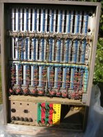
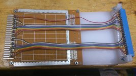
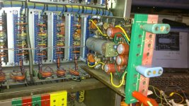
I now have a way to work on the cards outside the rack. Detached then end socket from the back of the rack and turned it through 180 degrees, about the vertical axis. I can now plug a card in the back and get the scope onto the card. Trouble as they are DC coupled its going to be fun debugging them....

luvit
Experienced Member
this is crazy cool, dave.
Moonferret
Experienced Member
That looks awesome. Sure you'll have it running in no time 
g4ugm
Veteran Member
Well some of it runs now! But I think getting it all running will be fun... Things I think should work don't, and things I think shouldn't work do. So the PSU and Reference Voltage Generator work fine, but the Reset/Hold/Run switch was totally gunged up. I had to prize it apart and clean the gunge out. I know its switching relays but there is a snubber network on the back to prevent the bigger spikes.. I was a bit worried about the Meter but it seems to work reasonably well.
What I am missing are some resistor plugs to go on the inputs of the amplifiers but I think I will replace some of the blank panels with resistor panels. Sadly no time to play tonight, got to finish a talk for some students tomorrow....
What I am missing are some resistor plugs to go on the inputs of the amplifiers but I think I will replace some of the blank panels with resistor panels. Sadly no time to play tonight, got to finish a talk for some students tomorrow....
Chuck(G)
25k Member
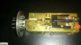
Dave, is that gray thing in the middle of the photo a mechanical chopper relay? Haven't seen one of those since the 1960s.
g4ugm
Veteran Member
Chuck,
Yes both the TR-10 and TR-20 use mechanical chopper relays to stabilise the op-amps. They are driven by 6.3V AC from the mains transformer so chop at 50 or 60hz depending on the country you are in. I think the high speed integrator blocks in the TR-20 also use the same relays to switch the integrator capacitors when running repetitive mode.
Dave
g4ugm
Veteran Member
Makintg progress
Makintg progress
OK Great Progress today.
Simple things first, went to a local Ham Rally and managed to buy a plug to fit the mains socket, so I can now connect it to the power without using a bodge.
Next , as I said above on testing the Amplifier circuits seem OK but the choppers are not chopping. They are in a B9A valve socket so also bought some B9A bases at a rally....
Next I added a couple of 4mm wander plugs on the back panel and tapped into the 6.3V AC that drives chopper relays.
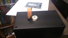
Then I built a box with a B9A on the top and some wander plugs so I get the AC to a "Relay Under Test".
The relays have a horseshoe type electro-magnet at the top, and a finger that wobbles to work the switch. On the faulty switches it looks like the magnets had corroded and there was "rust" stopping it from operating. Cleaned out the gunge and they all work again.
Amazing!
Makintg progress
OK Great Progress today.
Simple things first, went to a local Ham Rally and managed to buy a plug to fit the mains socket, so I can now connect it to the power without using a bodge.
Next , as I said above on testing the Amplifier circuits seem OK but the choppers are not chopping. They are in a B9A valve socket so also bought some B9A bases at a rally....
Next I added a couple of 4mm wander plugs on the back panel and tapped into the 6.3V AC that drives chopper relays.
Then I built a box with a B9A on the top and some wander plugs so I get the AC to a "Relay Under Test".
The relays have a horseshoe type electro-magnet at the top, and a finger that wobbles to work the switch. On the faulty switches it looks like the magnets had corroded and there was "rust" stopping it from operating. Cleaned out the gunge and they all work again.


Amazing!
mojorific
Experienced Member
Wow - fantastic work! Looking forward to seeing more progress!
m_thompson
Veteran Member
The RCS/RI people, just south of Boston, have the same machine.
http://www.rcsri.org/collection/pace-tr-10/
The Rhode Island Computer Museum has your machine's big brother.
https://sites.google.com/a/ricomputermuseum.org/home/Home/equipment/eai-580
http://www.rcsri.org/collection/pace-tr-10/
The Rhode Island Computer Museum has your machine's big brother.
https://sites.google.com/a/ricomputermuseum.org/home/Home/equipment/eai-580
g4ugm
Veteran Member
Thanks for those, I knew Rhode Island Computer Museum had the 580, but I didn't even know that RCS existed. Their TR10 actually looks rather sad with the missing modules or blanking plates. I wonder if the have a service manual?
I do hope to come to the east coast this year and visit the Rhode Island Computer Museum and MARCH. Not sure if I have time for RCS/RI as well...
I do hope to come to the east coast this year and visit the Rhode Island Computer Museum and MARCH. Not sure if I have time for RCS/RI as well...
billdeg
Technician
We have a few EAI experts at MARCH and I think the same model computer, on display, as yours. .. or the 20? EAI is from the state of NJ in USA.
Do you have all of the necessary hardware manuals?
I personally have never worked on the MARCH EAI machines but I seem to remember they're complete.
Bill
Do you have all of the necessary hardware manuals?
I personally have never worked on the MARCH EAI machines but I seem to remember they're complete.
Bill
g4ugm
Veteran Member
I have the tr-20 manual as a PDF, its 95% the same as the 10, but it would be nice to have the real ones. I have a book of application notes which I plan to scan. I also found a US Navy service book for a very similar amp which I guess might have been used in gunnery computers. That uses the same chopper, and has adjustment instructions in for that.
My next move is to replace one of the blanking plates with a panel with 10K and 100K resistors as I don't have any of the 4mm plug & socket with series resistor in ...
My next move is to replace one of the blanking plates with a panel with 10K and 100K resistors as I don't have any of the 4mm plug & socket with series resistor in ...
g4ugm
Veteran Member
I scanned the operators manual that came with the TR-10 and its now at Bitsavers in the EAI TR-10 folder.
g4ugm
Veteran Member
g4ugm
Veteran Member
More Tests - Simple Adding
More Tests - Simple Adding
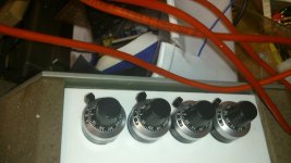
Well as I have my PC Scope back I can try a few "Programs" and display the output on the scope. I have now tried several "Programs". So first use the two new Pots to add voltages. Plug the system so the +10v Reference goes to the top of the calibrated pots and the wiper goes to one of the amplifiers. So the input can be read off the pot. Here is the wiring:-
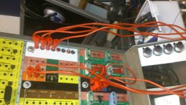
Here are the pots set to 5 and 3...
Here is the output. It should be "8" but the reference voltages are a bit low.
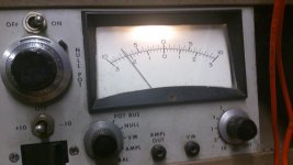
Also note its "-8" as the adder inverts.
More Tests - Simple Adding
Well as I have my PC Scope back I can try a few "Programs" and display the output on the scope. I have now tried several "Programs". So first use the two new Pots to add voltages. Plug the system so the +10v Reference goes to the top of the calibrated pots and the wiper goes to one of the amplifiers. So the input can be read off the pot. Here is the wiring:-

Here are the pots set to 5 and 3...

Here is the output. It should be "8" but the reference voltages are a bit low.

Also note its "-8" as the adder inverts.
g4ugm
Veteran Member
Ok I now have the pen plotter connected. Photos of a couple of plots are in my blog here:-
http://www.vintage-computer.com/vcforum/entry.php?504-Produced-more-complex-plots-on-the-TR-10
A video is on YouTube
https://www.youtube.com/watch?v=aLBSBqaVcxc
http://www.vintage-computer.com/vcforum/entry.php?504-Produced-more-complex-plots-on-the-TR-10
A video is on YouTube
https://www.youtube.com/watch?v=aLBSBqaVcxc

