• Please review our updated Terms and Rules here

Tektronix 4052 Troubleshooting

nikola-wan

Veteran Member
Joined
Mar 7, 2018
Messages
1,302
Location
Texas, USA
I made progress on my Tektronix 4052 troubleshooting today - the last power problem I debugged was a short on +15V2 power on the Display Board. It was the filter capacitor on that board.

I replaced the cap and with 15V now working - was performing display calibration.

The characters including the cursor show as a couple of dots (actually a small arc).

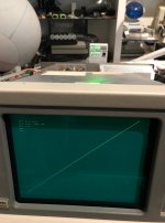
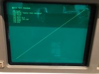
I typed a short program to see if it would draw a line - that worked.

100 MOVE 0,0
110 DRAW 130,100
120 END

Here is the screenshot:

4052 line ok but not characters.jpg

Now I need to debug why the characters look like arcs or short lines

Monty
 
I also bought several Cherry keyswitches to replace broken keys on my 4052 and 4054.

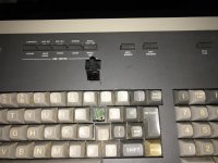
Here is a photo after I unsoldered the "P" key and the used a small exacto blade to remove the switch from the front of the keyboard.

IMG_6656.jpg

The broken actuator keyswitch is above the main keys - you can see the two holes in the circuit board.
I used solder removal braid to clear the solder from the holes.

Monty
 
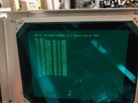
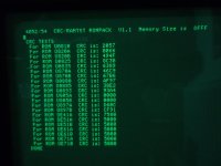
I just tried Jos Dreesen's 4052/4054 diagnostic ROM Pack http://www.vcfed.org/forum/showthread.php?63025-Tektronix-4052-54-diagnostic-ROM-pack-remade this morning - first test ROM CRC check to see if maybe I had a bad ROM.

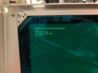
Test appears to complete without errors with similar number of ROMs checked ok (I count 21 test lines).

4052 CRC test complete.jpg

Not sure I set the DIP Switches correctly yet - Switch 1 (DRP enable) and 4 (I think CRC test 2) are on
During running the test or after pressing the DRP reset button - I see LEDs 1,2 and 3 are on.
When the test completes all DRP LEDs are off

4052 CRC LEDs during test.jpg

Monty
 
Last edited:
Ran all Diagnostic ROM Pack tests (switch 1 on, all others off) - no errors

4052 ran all Diagnostic tests - no errors.jpg

Then turned off the 4052, changed switch 1 to off (disable tests), turned on 4052 and entered my single-line DRAW program - line ok.
All DRP LEDs were on when pack tests were disabled.

No tests - draw line OK.jpg

Looks like I need to put the scope on the I/O board section for character D/A

Monty
 
WRT Leds : that is correct behaviour for the test pack.
Note that you can change dipswitches without having to switch off the TEK.
You only need to power down when inserting/removing the pack.

The CRC test just lists the calculated CRC's. It does not say "good" or "bad", AFAIK.

Jos
 
Hi guys, thought I'd join in after all.

Good to know that you don't need to power cycle when reconfiguring the DRP -- the PSU will thank you for it. My DRP rebuild is almost done, I'm still waiting for RAM a few other bits. Will be home next week to try it out on my 4052.

Congrats to Monty on fixing the power problems! Despite all the faults I had to deal with, the PSU was, surprisingly, up to scratch. It blew both fuses on the unregulated 20V supply, but that might have been a side effect of reversing the tape connector, which also feeds off this supply. (The direct effect was of course 3-4 blown 74xxx chips!) :huh:

That display problem looks odd; knackered 6821 PIA on the I/O board? Keep us posted!

--Roland
 
Almost got my 4052 fixed tonight

Almost got my 4052 fixed tonight

Looks like I found the root cause of the weird character issue - U1 a 7405 inverter was blown on the I/O Board. This inverter drives the vector X/Y filters - and because it was always asserted, the character dots were munged together. I tried pulling out the leads for the 'A' inverter and wiring the signal to the 'B' unused (I think) inverter but that didn't work either. It seems like only three of the inverter sections are used - the other two are on the GPIB page driving the interrupt line.

Here is my screen with me temporarily grounding the output pin of the A inverter:

4052 text on screen.jpg

Yippee! text.

I have ordered a 7405 from Mouser Electronics - should get it early next week.

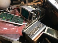
In order to find the cause of this issue I pulled out the board assembly under the display as shown in this picture:

4052 ready for debug.jpg

I left all the boards bolted together - but needed to plug the main power connector from the power supply.
I did put a big sheet of pink poly under the boards and under the keyboard.

I temporarily removed the longer power cable in my 4054 - but it still wouldn't reach.
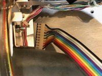
I found a solution - an EBAY seller had a 10 position 0.157 inch spacing pin header. I pushed the pins evenly centered on the plastic holder.
Then with both cables connected - I was able to power on and begin debug. The service manual says you need the power extender cable - but gave no part number.

Here is a picture of a header connecting the two power cables as an extender:

4052 power pin header.jpg

I will do another calibration on the cursor and character intensity after I replace the 7405.

Monty
 
Last edited:
Looks like I found the root cause of the weird character issue - U1 a 7405 inverter was blown on the I/O Board. This inverter drives the vector X/Y filters - and because it was always asserted, the character dots were munged together.
Way to go, Monty! I wondered about the purpose of the filter, until it became clear to me that any D/A conversion introduces discontinuities. I'm still confused as to when it's actually supposed to be active, since it munges stuff together as you say. The tech manual suggests that the X/Y filters use matched components, so replacements would infact have to be symmetric. The 7405 is however shared.

In order to find the cause of this issue I pulled out the board assembly under the display as shown in this picture:
Yeah, this is the major PITA when troubleshooting these. I wound up completely removing the board sandwich and the PSU and setting it up on my bench for ex-situ testing. There's just no way to really work on these inside the cabinet. I didn't have the luxury of an extender tho, so the exposed PSU sat right within reach -- albeit on an isolation xformer. :???:

Happy calibrating,

--Roland
 
Roland,

I think the filter keeps the two separate PIA writes to get 10 bits of DAC output on x and y from disturbing the current x/y position (output of the x and y op-amps), then when the VEN is active the beam starts from there and draws the new vector.

This filter then must be off for the quick dots needed for cursor and character text.

Monty
 
Tektronix 4052 Diagnostic ROM Pack test results

Tektronix 4052 Diagnostic ROM Pack test results

While I am waiting for the 7405 inverter - I decided to jumper the inverter to ground to force characters to work.

I plugged in the Serial Backpack and Jos Dreesen's design of the 4052/4054 Diagnostic ROM Pack
http://www.vcfed.org/forum/showthread.php?63025-Tektronix-4052-54-diagnostic-ROM-pack-remade&p=509488#post509488

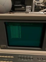
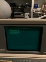
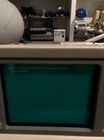
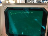
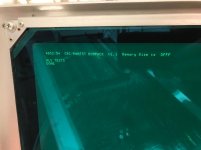
and ran the ROM CRC Test, ALU Test and long and short RAM tests - all with no issues found. Here are the three screenshots of the test results:

My 4052 ROM CRC test.jpg

RAM test.jpg

ALU Test.jpg

The documentation Jos supplies with his board includes the Tektronix 4052/54 ROM CRC results.

I have 4052 V5.1 ROMs - no patch ROMs and they all check out fine according to the list.

The DFFF RAM size is correct according to the documentation for a 64KB memory system (with a chunk taken out for the I/O space).

Thanks for a great diagnostic board - Jos!!

Monty
 
My 4052 text issue is now fixed

My 4052 text issue is now fixed

I couldn't wait for delivery of the 7405 inverter - so I went to the Houston EPO Surplus Outlet and picked up a couple of 7405 - and several NOS old capacitors that I may need to fix my 4054.
In fact I did some more 4054 power supply tests and it appeared the output 5V cap (250uF 20V) was not working.

This morning I carefully unsoldered the bad 7405 and cleaned flux off the board and soldered in the new one.
I ohmed the "A" inverter section and the other two I could see traces for - and all three connected up to the traces.

I put the board assembly back together - bolted into the chassis, powered it on - and I had text and graphics!

IMG_6747.jpg

I then did some calibration on text and cursor intensity before putting the cover back on.

Monty
 
Hi all,

just to let you know I finished my DRP and it was up and running straight away -- thanks, Jos! :thumbsup:

My 4052 passed the short and long RAM, as well as the ALU tests. The CRC test (see below) agrees with the published checksums for the v5.1 firmware (on a rev9 MAS in my case), but the U805A/B and U897A/B results leave me puzzled.

DSCN0723.jpg

According the checksum documentation, these are "valid extensions" of U820 and U870 for the v5.1 firmware and for the 4052A, because there IS no U805 and U897 installed. In these cases, the following correspondence holds:
  • U805A --> U820C
  • U805B --> U820D
  • U897A --> U870C
  • U897B --> U870D
Can anyone make sense of this? What exactly does U820C/D and U870C/D mean, considering those chips have already checked out OK a few lines above in the DRP output?

I'll have to check if my rev9 MAS does infact omit the patch ROMs U805 and U897 to verify this output. I'll have to dig thru my previous photos, but failing that, I might have to actually pull the entire board assembly again. :(

Best regards,

--Roland
 
Hi all,

Can anyone make sense of this? What exactly does U820C/D and U870C/D mean, considering those chips have already checked out OK a few lines above in the DRP output?

--Roland

Roland,

That is puzzling. I read the notes after the CRC list and it is still not clear why they would report those - unless the 820 and 870 ROMs actually contain multiple smaller images - each with a checksum.

I found the ROM images I captured with my Data I/O and notes I took after purchasing my 4052 in 2000 - but apparently I upgraded my ROMs since then as those images are v4.1 and now I have v5.1.

Monty
 
Old tape drive belt replaced - but now screen is bad

Old tape drive belt replaced - but now screen is bad

Good news and Bad News on my 4052 today.

Good news was - I transplanted a drive belt from a NOS Imation DC6250 tape to an old cartridge with a disintegrated drive belt - and I think it worked, but my screen had gone bad (bad news) :(

The process of replacing the QIC cartridge drive belt is documented elsewhere on this forum and on the web. Recommended practice was buy a new DC6150 tape and transplant that drive belt to an old cartridge.

I decided to buy DC6250 cartridges since they are newer than the recommended DC6150 cartridges.

Today I received seven NOS Imation (3M) DC6250 cartridges I ordered off EBAY.

I unwrapped the first one - belt looked fine and the tape moved when I pushed on the drive wheel.

I then plugged it into the 4052 and typed CALL "MTPACK" to fast forward and rewind the whole tape - took about 4 min 30 seconds.

I then typed a short program:

100 PAGE
110 PRINT "File 1"
120 END

and then save it to the tape:

FIND 0
MARK 1, 510
FIND1
SAVE

then I pressed autoload and the screen cleared and I saw File 1!! :)

Emboldened - I decided to put that tape aside and open a second tape to transplant that belt to an old tape from dozens in a box I purchased from Stan Griffiths almost 20 years ago.
I was able to transplant the good belt to the old cartridge.

Although the belt had completely broken in that cartridge there were small pieces of the now white belt still hanging onto the tape from both reels.
I carefully moved the tape to the belt pulleys and pushed on the reels to get the tape with the pieces of belt on the pulley - and when I touched the bad belt piece it would flake off.
However, there were shiny strips on the tape that had been against the bad belt. I tried carefully wiping those spots with a swab - but they didn't come off (or the oxide was completely removed).

Before using the old tape - I checked the tape head and decided to clean it with isopropyl alcohol on a short cotton swab clamped in a hemostat (surgical clamp).

I put the old tape in the 4052 and noticed the screen had gone bad - but continued anyway.

I did MTPACK on the old tape - it completed and I pulled out the tape and both reels looked nice and packed.

Since a tape listing in that old tape box indicated the first program was an autoload menu - I pressed autoload and the screen cleared and lines of text printed (that I couldn't read).

Here is the screenshot of pressing autoload to get the first program loaded
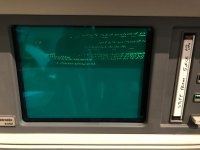
IMG_6792.jpg

After pressing Break twice to stop that program - I took this screenshot - the last line looks like PROGRAM (ABORTED...) - but from right to left and the characters are stretched.
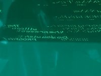
IMG_6793.jpg

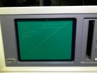
I then typed in my program to draw nested lines - and it didn't work - so I will now begin debug of the X and Y DACs and output circuit :(

Another clue - after leaving my 4052 off for more than 30 min - when I first turned it on I had a good blinking cursor and text, but only a minute or two later the cursor started wildly moving left and right rapidly, then the cursor was gone and typing characters resulted in the weird text again.

I think it is an X output issue. I'll remove the main boards and get a scope on the X output on the I/O board. Maybe it is a bad opamp? If the voltages check ok and the output is bad - it must be the opamp.
If that is the case - fortunately the MC1458 op amp is still in production - and my local Fry's has the NTE778A replacement part in stock.
 
Last edited:
I am stumped :(

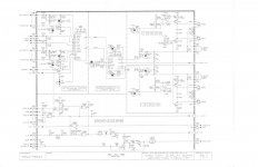
I have probed my 4052 Display Board X and Y output sections - see following schematic page for the Deflection Circuitry that drives the yoke on the CRT neck:

4052 Display Board Deflection Circuitry A6-1.jpg

Here is a better resolution link to that scan - https://drive.google.com/file/d/1FQxqfVyOeA1BJjUS7b7X-FzL7Wb8g7q5/view?usp=sharing

The X and Y outputs from U485 in the middle of that schematic are clean (no noise).

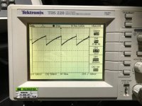
The problem is the input and output of the U184A op-amp have a ramp oscillation waveform - see this scope picture:

oscillation on opamp input.jpg

Frequency is 37.5Hz and 1V peak-to-peak. And the output transistors drive the yoke with that waveform which is what is distorting displayed characters and lines :(

I have changed out C196 across the zener diode - where I also see the oscillation, and the +20V capacitor at the +20C input to the display board to no effect.

I also swapped the cables to the similar output transistors on the Y-axis - but that didn't change anything either.

The +15V and -12V inputs to the op-amp have no noise.

I just scanned my 4052 Tech Data Service Manual section 11 which covers 4052 Display theory of operation - here is the link:

https://drive.google.com/file/d/1Zna3wZz_6RHvhCodQRj0PFJl5TY-6NE4/view?usp=sharing

Page 11-12 briefly discussing the deflection amplifier circuit and mentions "The GAIN adjustment provides a feedback voltage from the coil current sensing resistors to set the amplifier gain".
I tried tweaking the X GAIN pot R270 slightly - it didn't seem to change the oscillation - but hard to tell.

There is less detail on the deflection circuit than in the 4051 Service Manual display section - I scanned two pages of that section - here is that link:

https://drive.google.com/file/d/1bxiVouBC2mVsXTdcRM0q227eUtc8vKcT/view?usp=sharing

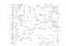
and here is the 4051 Deflection Circuitry schematic page - looks just like the 4052 diagram with different numbering on the components:

4051 Deflection Circuitry 4-5.jpg

and a higher resolution link for that schematic page: https://drive.google.com/file/d/1TJjeZqszca1C7XILsnDyO9D_r64ZMwoo/view?usp=sharing

Anyone got any ideas?

Monty
 
Last edited:
What about the inputs and output from U184B? Is that the same or not?

Since you see it on C196 (and have changed that), I would concentrate there...

What about the Zener diode VR196 itself?

What about the -20V supply? The other end of the zener/capacitor is connected to -20V.

If it is something to do with the zener/capacitor/power supply it should be common to both the X and Y circuitry.

The problem you have is that any disturbance to the output will 'feedback' to the input via the circuitry containing C175.

Just don't damage the resistor pack R74. They are very, very expensive to replace! I am speaking from experience...

Dave
 
Last edited:
Good news and Bad News on my 4052 today.

Good news was - I transplanted a drive belt from a NOS Imation DC6250 tape to an old cartridge with a disintegrated drive belt - and I think it worked, but my screen had gone bad (bad news) :(

The process of replacing the QIC cartridge drive belt is documented elsewhere on this forum and on the web. Recommended practice was buy a new DC6150 tape and transplant that drive belt to an old cartridge.
Hi Monty,

congrats on getting the tape drive working -- mine gave me some headaches and of course I had belts failing all over the place. I noticed you do have to remove oxide shed regularly from the heads when reading the old tapes. I also had sticky-belt syndrome with residue on the tape, but apparently the tapes were all rewound and the data area wasn't affected. I've heard of a number of "fixes" to remove the belt residue, ranging from isopropyl to furniture polish. YMMV...

Btw, my capstan motor whined insufferably; a few drops of silicone lubricant down the spindle made a big difference. The capstan roller itself is remarkably well preserved; whatever rubber formulation Tek used, it turned out to be a helluva lot better than that used by HP and TI in their card readers and tape drives.

I'm stumped about that display problem too -- will follow this closely, but don't think I can contribute anything useful. Good luck!

--Roland
 
The problem you have is that any disturbance to the output will 'feedback' to the input via the circuitry containing C175.
Maybe a dumb question, but could this disturbance originate inside the CRT?

--Roland
 
It shouldn't do. The circuitry is associated with the deflection circuits, so it would be an unlikely interaction between the tube and the circuitry, unless something is feeding back from the tube to the power supply rails - but that is always why you should check all of the power rail voltages (both dc level and 'noise') before looking at anything else.

I will, hopefully, get back to my Tek 4052 microcode emulator shortly. I have gotten distracted by paying work again and an 8008 emulator (that is predominantly working now).

Dave
 
Back
Top