• Please review our updated Terms and Rules here

Help identifying horizontal linarity coil inductor

SomeGuy

Veteran Member
Joined
Jan 2, 2013
Messages
4,441
Location
Marietta, GA
Click image for larger version  Name:	inductor.jpg Views:	0 Size:	11.0 KB ID:	1218017
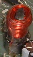
I posted this in another thread, but I am trying to identify and locate a replacement for this damaged inductor on the CRT board of a Columbia Data Products VP portable/luggable.

I'm just having no luck at all finding information about it online. All I know is it is used for horizontal linearity. No idea as to the "uH" rating, or any other ratings. A couple of snippets here and there suggest that a regular inductor is different from a "linearity" inductor somehow? If that is so, then are there any suitable replacements at all?
 
The linearity coil is different from a regular inductor, in that it contains a permanent magnet. So its inductive properties are in themselves not linear.

The idea is to correct for the non-linearity that is intrinsic to the H scanning system in all magnetically deflected CRTs.

There are two basic problems with the linearity in magnetic H scan, the first is that the yoke has an increased sensitivity for higher deflection angles, this results in general compression of the raster centrally or relative expansion at the R and L sides, this anomaly is corrected by the S correction capacitor in series with the H scanning coils of the yoke.

The remaining linearity problem is more interesting, as in the case of H scanning: essentially a rectangular voltage is switched across the yoke by the HOT (horizontal output transistor). The current climbs initially at least linearly at a rate of V/L where V is the supply voltage and L the inductance, but starts to taper a little near the right side of the scan. This partially compensates some of the yoke increased sensitivity. Unfortunately though, when the HOT is switched off for flyback, the field in the yoke gets reversed after flyback, beam on left side of screen, and the rate of change of current with time is initially higher than it was on the right side of the raster, in the initial part of the scan, as the current then passes (decays) via the damper diode back to the power supply to scan the left side of the raster.

The net effect is, the scanning raster, without a linearity coil in series with the yoke, in a transistor VDU, will always be a little stretched on the left side, and a little compressed on the right, even if the the S correction capacitor is ideal.

Some linearity coils, the magnet is a metal cylinder with a hex hole that rotates adjacent to the coil. After a while many manufacturers made fixed linearity coils, non adjustable with the magnet built in.

If you cannot find the exact part one option could be to search for TV linearity coils on ebay and find an adjustable one that can also be rewound with a similar sized wire and number of turns, to the one you are trying to replace. Generally these coils use fairly thick wire as adding DC resistance degrades the linearity.

A width control inductor on the other hand, has no magnet and simply reduces the overall H scanning current and reduces the width of the raster proportionally without changing the linearity.

Very early transistor TV sets of the 1960's had no S correction capacitor and no linearity coil, the Sony Micro-TV 503E being a good example, and its H scan linearity shows both the defects. Other early TV sets such as the Sanyo 8P-2, just had the S correction capacitor and no linearity coil. By the 1970's practically all TV sets and computer VDU's had both. If you are interested to see raster H scan linearity defects when one or both of these components are missing, there are some photos on this article, see pages 8-15:

https://www.worldphaco.com/uploads/S..._from_1962.pdf


Edit: Don't be confused by "linearity" coils you see on ebay for Tube TV's. These are plain inductors with no magnets. They work differently. In the case of a Tube set, to adjust the H linearity, it is done with a plain adjustable inductor, tuned with a capacitor, to add a parabolic like voltage in series with the output tube's supply voltage to control the shape of the yoke's H coil current wave.

Here is a transistor Lin coil, the magnet is on the top, not adjustable and glued in place by the factory:

https://www.ebay.com/itm/28412270255...QAAOSwjV9f4Mdj

I'll look around and see if I can find some tool adjustable ones.They seem hard to get these days. Here is another fixed one:

https://www.ebay.co.uk/itm/142861716477?hash=item214338cbfd:g:YWUAAOSwgKBaotdw

On these fixed ones it may be possible to free the magnet on the top to make them adjustable by rotating it.

Or, you could try adding a rare earth button magnet to the top of your broken coil, space it from the top if required & rotate it for best linearity and glue it on with epoxy resin.
 
Last edited:
Great, now I'm more confused. The inductors I have been looking at on Mouser are ferrite core inductors. Ferrite is magnetic, isn't it? Or are we just talking about a stronger magnetic core? What core material is in a linearity coil then?

What you describe is what my CRT is doing. The image is stretched a bit on the left, and squished on the right. At least I don't BELIEVE there is anything else damaged on the CRT board.

There is indeed a second "adjustable" coil, that is supposed to adjust with, but the core won't turn or move.

The really annoying thing is that I did have the top broken part when I got it, but it disappeared.


Ferrite cores have magnetic properties, specifically of permeability, so if you slip a ferrite core into a coil, it increases the coils's inductance. This is why your Width coil is adjustable so you can adjust the inductance of it, as a way to control the width.

A current in a coil creates a magnetic field (H field, units of Amps per meter) or magetizing force. It is converted to a B field (flux density in Teslas, units Webers per square meter) by any magnetic material placed inside the coil, the relation is B = UoUrH , where Uo is a constant of 4.Pi x 10^-7 and Ur is the relative permeability.

As an example a typical ferrite rod in a transistor radio has a Ur of around 125.

If you plot a B-H curve of some inductor with a ferrite or iron core, it is not linear, more of an S shape and it is split into a hysteresis loop. So you can push the magnetizing force to different places on the curve by applying more coil current..... or by adding a permanent magnet, thereby magnetizing a core. Just for one example, you can make a pulse transformer that will only respond to one polarity of an applied pulse if you use a magnetized core, because the core is already magnetically saturated high up onto the horizontal part of the B-H curve, by the permanent magnet. An even cleverer trick is to use a material like Alnico, and and an added high current coil, to magnetize it in each direction, so you can control if the transformer accepts a pulse or not. This was a method that very few people know about to make a shift register,without tubes or transistors prior to the dawn of digital electronics, but getting off topic.


The Liniearity coil also contains ferrite, but in addition contains a permanent magnet. This makes the ferrite core and inductance behave in a non linear manner, hence able to adjust the scan current asymmetrically, hence the scan linearity. Most of the modern coils were made fixed for any VDU's, with the magnet disc mounted on the coil top, earlier types had a magnet mounted beside the coil.

Most coils/inductors you see on Mouser are just ferrite cored inductors with no magnets, I have never looked on Mouser for a magnetic linearity coil, I doubt if there is one at Mouser.

As noted most of the Linearity coils on ebay are for Tube sets that have a different operating principle, and no magnet.

This is why I posted those ebay links to show you the coils with the magnets.

For any given VDU design, the linearity coil became a custom made fixed part for most manufacturers, not an off the shelf part. The coil inductance and the specific magnetic field applied to that by the permanent magnet has to be exactly correct. So to replace this with another type, ideally its an adjustable version.

(One reason on a width coil, especially the type with a hex hole in it, won't rotate, is a hairline crack on the long axis of the slug than can occur if a metal rather than plastic tool is used. If this has happened, as the tool rotates the slug expands and the cracked edges bind in the threads and it refuses to rotate. If this has happened there is a method to get it to rotate again for removal)

I found a picture online of the type of linearity coil that has a cylindrical shaped magnet next to the coil , which rotates so that the horizontal scan linearity can be manually adjusted:

https://electronics.stackexchange.co...weird-inductor

If you could get an adjustable linearity coil it would be almost certain you could get your linearity perfect. Or as I suggested add a magnet to the top of your broken coil and attempt to position it for best linearity. Most TV repair stores had defunct pcb's with these adjustable Lin coils on them, but it seems as time passes, and CRT technology became obsolete, these resources are less common.


This looks highly likely to solve your problem:

https://www.premmagnetics.com/mechan...-peak-maximum/

They come in different inductance and max current ranges, you may have to do some experimentation, but at least you will have an adjustable coil to work with.
 
Last edited:
Thanks very, very much for the detailed information.

Any opinion on these? https://www.premmagnetics.com/crt-display-magnetics/mechanically-adjustable-linearity-coils/
I don't know if those would quite fit on this board.

Ok, so different ferrites. I see now the entire core is permanently magnetized (what is left in that coil seems to attract my screwdriver).

Good to know about attaching the top magnet in the right direction. That makes sense, If I hadn't lost that top I probably would have glued it on wrong.

Customized for each design.... That explains a lot. So no real hope of finding a pre-made direct replacement component other than parting out an identical machine with with same model of CRT board.

That adjustable core.... facepalm. Yes, it's cracked. I think it was already damaged due to other existing damage. But I did try using an Allen wrench. So let this be a warning to future generations - do not use a metal Allen wrench to adjust a ferrite core. So what is the trick to remove it? And where does one find a plastic Allen wrench?
 
Thanks very, very much for the detailed information.

Any opinion on these? https://www.premmagnetics.com/crt-di...nearity-coils/
I don't know if those would quite fit on this board.

Ok, so different ferrites. I see now the entire core is permanently magnetized (what is left in that coil seems to attract my screwdriver).

Good to know about attaching the top magnet in the right direction. That makes sense, If I hadn't lost that top I probably would have glued it on wrong.

Customized for each design.... That explains a lot. So no real hope of finding a pre-made direct replacement component other than parting out an identical machine with with same model of CRT board.

That adjustable core.... facepalm. Yes, it's cracked. I think it was already damaged due to other existing damage. But I did try using an Allen wrench. So let this be a warning to future generations - do not use a metal Allen wrench to adjust a ferrite core. So what is the trick to remove it? And where does one find a plastic Allen wrench?

Snap, we found the same link to that lin coil, I had just added it a while before you posted.


To remove the cracked core or slug in the width control: The best way to do it is to hand carve a wooden hex tool with a scalpel blade, strong wood, a chopstick works, make it as geometrically perfect as you can, to slip into the hex hole in the slug but not a tight fit. Then, before inserting it again, coat its surface a little with 24 Hr epoxy resin where it contacts the slug interior, don't use too much, if the glue gets to the slugs threads its game over. Then gently insert it in the slug and don't touch it for 24 Hrs. When it dry, you end up with the two halves of the slug glued to the sides of the tool, then when you rotate the tool, the slug halves don't separate / expand and you can unscrew & remove the slug.
 
You can (still) find nylon alignment tools. For example. Using a steel tool to adjust a coil slug is a bad idea if you're trying to watch the screen while you're working. The tool will disturb the coil properties and things will change once you remove it. Also, a steel tool will often heat up (inductive heating) and jam itself into the core and break it.
 
So I tried one of those Premmagnetics adjustable linearity coils, but all it did was damage the 100 ohm resistor at R431 and blow out the new linearity coil. It did look a little smaller than the old linearity coil, but there was no way to tell from a bunch of identical stock photos.

I did get some little round refrigerator magnets that look pretty sitting on top of the old linearity coil but does not change its behavior noticeably.

I guess this entire CDP VP is FUBAR due to a stupid broken magnet.

Oh, and I measured the inductance with a crappy little "DM4070", and according to that, the broken linearity coil is about 37uH, and the variable width inductor is about 15uh.
 
Back
Top