• Please review our updated Terms and Rules here

Setting up GBS-8219 CGA to VGA Converter

xpower

Member
Joined
Oct 18, 2015
Messages
34
Location
Swansea UK
I’m trying to setup a GBS-8219 XVGA CGA to VGA conversion box to connect a Tandy 1000TL to a VGA monitor.
I’m using a rhinocables Serial Null Modem Cable was described as “DB9 Female RS232 For Computer EGA Monitor TV” and a pin adapter to connect the computer to the converter.
I’ve tried changing the menu options but there is no signal passing through the box.

What should the menu options be to convert a CGA signal?

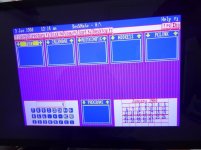
These are the menu options shown on the screen.


P1010736.jpg
 
Looking up the terrible excuse for a manual for this thing "RGB(D)" under "Style" and "SEPARATE(HV)" under "Sync" should be correct. I think the problem is you say you bought a "Null Modem" cable; that's wrong. A Null Modem cable swaps several pairs of wires around so two serial ports of the same "gender" can communicate; you need a straight-through cable for this.

FWIW, this is going to do kind of a bad job for digital CGA conversion. (Something to be aware of is in the world of these scan converters "CGA" is often a synonym for "RGB at NTSC TV frequencies". This is what many arcade boards use. Unfortunately they use the analog flavor of it.) According to the manual in digital mode this only has the "RGB" pins; it does not look at or process the "intensity" pin. Therefore you're only going to get 8 of the 16 colors. If you want this to display true CGA colors you're going to need a separate adapter to convert RGBI into RGBA like this and feed the output of that into this after changing "STYLE" to RGB(A).
 
Ok so, my experiences are with the bare GBS-8200 board, not with this 8219, so keep in mind as you read this that I may be full of poo.

I can't find a too much info on this 8219 online, as far as using it with pc-type TTL CGA connections. So....

Are you *SURE* that this thing really does support pc-type TTL CGA video input?

The 8200 that I've messed with claims to support "CGA and EGA", but they are actually referring to some kind of analog RGB modes that old arcade boards output. These are 15khz analog 0.7 vpp RGB signals with a digital composite sync signal. In contrast, pc-type TTL CGA is a 0-5v digital RGBI signal with separate H/V digital sync signals. What I had to do to get the 8200 to work with pc-type CGA was to (1) Convert the 5v digital RGBI signals into 0-0.7v signals using a resistive voltage divider, and a diode and resistor on the intensity line to halve the voltage divider when the intensity bit was turned on, iirc. I calculated my values assuming a 75 ohm built-in termination on the GBS-8200 board, but the signals were too low. I ended up using variable resistors as the voltage divider and calibrating it to 0.7vpp using an oscilloscope. I also had to (2) use an XOR gate to combine the sync signals, as the 8200 will only accept separate sync on signals 31.5kHz or higher.

The results were usable, but not ideal. After finding that my calculated values didn't produce the desired results and doing everything with variable resistors, I was never able to get the middle-intensity signals quite right. Also, additional logic is required to properly convert the grays and brown color to display correctly. One of these days I plan to redo it with a 22v10 GAL that takes in RGBIHV and outputs 2-bit EGA type digital RGB (which I can then convert to .7vpp analog video with a resistor ladder) and csync.

Also, of the 3 GBS-8200 boards I've ordered, the first one was DOA and the second one was noisy as heck. #3 worked correctly, but it was a pain to go through the ebay replacement process with the rather sleazy far-east seller twice. I was able to get the second board working by reflowing the big QFP chip, but my opinion after all that is that the Gonbes products are complete garbage. I'd make sure the 8219 really does actually support digital RGBI CGA input before tearing at it with a soldering iron, though.

Good luck. ;(
 
Last edited:
PS: If you don't want to make your own proper RGBI to analog RGB converter, I think gglabs sells one that is pretty highly regarded and does all the color conversion correctly.
 
Thank you both for your replies.
The only reason I bought that cable was that it had "for EGA Video" in the description but was I'm a bit unsure if it was correct. I will order a straight through one instead.

I made sure this is a PC CGA converter and not one of the Arcade GBS-8200 Video Converter which will require an additional board to work with CGA.

This video confirms that it should work as a PC CGA to VGA converter

LGR tested an alterative box (MCE2VGA) which had really good results but I didn't find until I was trying to trouble shoot the one I bought.

I will initially try a straight through cable. If that doesn't work then I really don't want to try and reflow the board so I will cut my losses and get the MCE2VGA converter instead.
 
I made sure this is a PC CGA converter and not one of the Arcade GBS-8200 Video Converter which will require an additional board to work with CGA.

This video confirms that it should work as a PC CGA to VGA converter

The video is about using it for MDA, which should work fine... except actually it doesn't, I'll get back to that. The issue is that this device only has three inputs in digital mode, "R", "G", and "B". CGA has four digital outputs, AKA, it's called "RGBI", and those four signals are the aforementioned RedGreenBlue PLUS an "Intensity" signal. This gives 4 bits total of color information for each pixel. 2^4 = 16. This converter doesn't know anything about the "I" signal so you're only going to get 2^3, or 8 colors. This isn't going to matter that much (probably) if you're buying this adapter to use for some piece of industrial equipment, but losing the distinction between normal and high-intensity colors is going to be a significant issue for a PC you might want to play games on (they won't look right). This will also affect programs that do colorful text displays; it's not rare for menus to use "Intensity" to indicate menu selections, for instance. With this converter you won't be able to tell what you selected.

... And to get back to what I said earlier, looking at what the guy in the video did he also did nothing with MDA's "Intensity" line, he just left it hanging. MDA supports "normal" and "bright" text, and with the way he wired that thing he's not going to be able to tell the difference. Maybe he doesn't care for his embedded application, but this would also be a problem for PC use.(*)

So while, yes, this board's native ability to treat the RGB lines as "Digital" means you can get "a display" from a digital CGA/MDA/EGA source, it's not going to look right. The only way to fix it is to use exactly the same converter board you'd use for a GBS-8200 externally and set this device to use analog input. That's disappointing because I strongly suspect the guts of this thing are nearly identical to the $20 GBS board.

(* If I were stuck using this for MDA and had no option to add an external adapter to turn it into proper shades of gray I would probably wire the "video" line to green and red, and the "intensity" line to blue. That would make the "normal" text color yellow and "intense" text white. Not a great solution but it's better than not seeing it at all.)
 
We could design a GAL-based proper CGA to analog RGB conversion device. We could use #septandy as an excuse and use it with our EX/HXen. Then I/we could maybe make one on protoboard and send to Mr. xpower so he can get his 8219 box working right. It's something I've been meaning to do for some time, but I have trouble staying focused when it's just me myself and I fooling around with things.........

I need to learn a little more about how the termination works on RGB connections. Looking at the schematic for the gglabs device, it appears that he already had this idea and uses a GAL in his too. But he puts the output of the resistor DAC into a video amplifier chip and then runs the output of that through 75 ohm resistors. I don't understand the need for the video amp IC, and why the termination can't just be part of the DAC bridge. But I am pretty ignorant.....
 
We could design a GAL-based proper CGA to analog RGB conversion device. We could use #septandy as an excuse and use it with our EX/HXen. Then I/we could maybe make one on protoboard and send to Mr. xpower so he can get his 8219 box working right. It's something I've been meaning to do for some time, but I have trouble staying focused when it's just me myself and I fooling around with things.........

I'd be willing to help out with that if you've got a GAL programmer. Earlier revisions of the GGLABS device didn't have the video amp, they were just a straight resistor ladder on the output side. The GAL equations per-se weren't posted but you could derive them from the manual, so it's been on my list for a while to get around to trying to toss one together anyway. (I even bought resistors for the resistor ladder in an IC order, sheesh, at least a year ago. Time flies I guess.) I suspect the video amp chip is in there to get a "cleaner" signal, but GALs are pretty muscular on the output side, I'd think it'd be okay for reasonable length cables?

The revision I'm thinking of also had a 244 or 245 on the input side for a buffer, and that kind of left me scratching my head why you'd want/need one in front of the GAL. My ignorant take is the GAL should be fine taking the CGA input directly.
 
Yeeeeee, lemme get galasm recompiled on this new machine and see what I can poke up for a pld file.

One conundrum is which intermediate 2-bit value per RGB channel to use for the low intensity CGA signal, 01 or 10. I guess it would about have to be 10. Easy to reprogram if I'm wrong regardless I guess.

I reckon 470 and 1000 ohm resistors would be about right... Yeah.

And now the procrastination begins!
 
One conundrum is which intermediate 2-bit value per RGB channel to use for the low intensity CGA signal, 01 or 10. I guess it would about have to be 10. Easy to reprogram if I'm wrong regardless I guess.

I reckon 470 and 1000 ohm resistors would be about right... Yeah.

Here's the design page for GGlab's oldest version of the board, they're using 1.37k and 681. I guess I misremembered, they're using an *output* buffer, a 74AC541, not an input buffer. Looking at the datasheet for the (current) ATF16v8 GAL it does have a substantially lower drive current than that buffer, but... yeah, I don't know how badly you really need it. I do suspect that it'd be worth fiddling with the output side to see if you can give it the proper impedance. If you have them lying around using an output transistor on each video line plus 75 ohm termination might do almost as well as that buffer they use in later models.

Don't forget that in the GGlabs boards the GAL is also programmed to convert separate sync to composite, which is what the GBS scalers want, but I suppose that might not be an issue with the thing the OP bought.
 
Last edited:
... another thing that would be worth doing (as implemented on later versions) is instead of limiting this to RGBI there are enough lines left over on the GAL to make it switchable for CGA/EGA/MDA output modes, so might as well. (There was a thread a while back about how EGA is a little iffy to do right because of how EGA changes sync polarity for the 350 line mode, therefore autoswitch is broken, so maybe just CGA and MDA is enough.)
 
Yeah, I was thinking maybe the GAL wasn't beefy enough to drive the video signal all by itself. I reckon if the voltage drops out I can stick an LS245 in there or something. I don't have any AS451s nor any of the video amp chips, but I have a truckload of 245s. But a 245 ought to handle all 6 bits of video as well as the csync and be beefy enough to drive a vga signal..
 
... another thing that would be worth doing (as implemented on later versions) is instead of limiting this to RGBI there are enough lines left over on the GAL to make it switchable for CGA/EGA/MDA output modes, so might as well. (There was a thread a while back about how EGA is a little iffy to do right because of how EGA changes sync polarity for the 350 line mode, therefore autoswitch is broken, so maybe just CGA and MDA is enough.)

Yeah, the gglabs design with the 16v8, I don't see how it could detect and deal with that weird EGA sync thing, so maybe it doesn't. Iunno. I assume all the games use 200 line mode, so maybe it doesn't need to.

PS: What's the deal with the 75ohm resistors in series with the output on the newest design? I thought source termination went to ground, not in series.... Am I confused?

Edit: I am confused. I guess source termination *does* go in series. Makes sense I guess. The purpose of the video amp must be to isolate the source signal from the R2R bridge so that the source impedance is correct so as to prevent reflections. I don't think I care if my video is a little dirty though. It'll add character and be more like my noisy ol' Tandy CGA monitor. :3
 
Last edited:
I wonder if we should start a new thread. Is it rude of us to use this one for this?

Heh, I guess it depends if the OP ends up wanting to try to improve the scaler they bought or not. But yeah, maybe it should go in a separate thread, maybe under "vintage hardware".

Sort of itching to break out the breadboard this weekend, but, man, I feel like I should play with my new TRS-80 that needs plenty of love...
 
Yeah, the gglabs design with the 16v8, I don't see how it could detect and deal with that weird EGA sync thing, so maybe it doesn't. Iunno. I assume all the games use 200 line mode, so maybe it doesn't need to.

In that thread a while back I think it was determined that you're probably stuck needing to flip a switch going between 200 and 350 line modes because, yeah, I don't think there's any way for a GAL alone to figure it out. (Maybe you could come up with some clever minimal-components system to measure the average voltage-over-time of a sync line to be able to guess at the polarity and flip the GAL mode for you. Sounds like a job for an ATTINY.)
 
Sort of itching to break out the breadboard this weekend, but, man, I feel like I should play with my new TRS-80 that needs plenty of love...

Yeah, I am *supposed* to be getting some code written before retrochallenge starts, but there are so many shiny things..........
 
PS: What's the deal with the 75ohm resistors in series with the output on the newest design? I thought source termination went to ground, not in series.... Am I confused?

Edit: I am confused. I guess source termination *does* go in series. Makes sense I guess.
"it depends"
The purpose of the video amp must be to isolate the source signal from the R2R bridge so that the source impedance is correct so as to prevent reflections.
Yes.
I don't think I care if my video is a little dirty though. It'll add character and be more like my noisy ol' Tandy CGA monitor. :3
Gross!
 
I got the straight pass through cable cable and tried that.
Surprisingly on first viewing it doesn't look too bad.

Monitor_Screen(1).jpg
Text in dos is readable as well.
Getting it working at all is a bit of a relief that it wasn't a complete waste of money.
I have ordered the MCE2VGA as well so I can make comparison between the two.
 
Back
Top