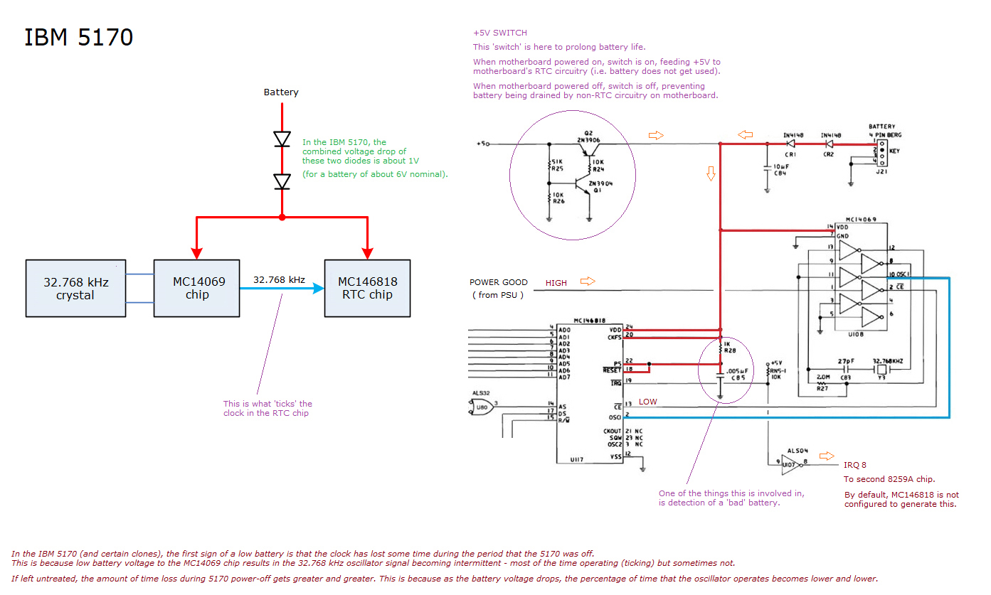
The resistor is not a requirement. It does drop some voltage, but without it, a new 6 volt Lithium is tollerated by the 5170 motherboard. I've had no problems using resistor-less 6 volt batteries.
A 163 error is a 'Time & Date not set' error. That error apears after the first part of SETUP configuration is done (memory size, hard drive type, etc.) but not the second part (date/time). I would expect GSETUP to correct that, but I've encountered issues with GSETUP. Have you tried the 5170 Diagnostics Disk? You can also try the following BASIC code:
REM Initialise A/B/C/D registers
REM and prepare for imminent setting of the clock
out 112,10
out 113,38
out 112,11
out 113,130
out 112,12
a = inp(113)
out 112,13
a = inp(113)
REM ----------------------
REM Set hour:minute:second to 19:00:00
out 112,0
out 113,0
out 112,2
out 113,0
out 112,4
out 113,25
REM ----------------------
REM Set day of week to 3 (where 1=Sunday)
out 112,6
out 113,3
REM ----------------------
REM Set date to 13Sep2011
out 112,7
out 113,19
out 112,8
out 113,9
out 112,9
out 113,17
out 112,50
out 113,32
REM ----------------------
REM Clock has been set - enable updates
out 112,11
out 113,2
")