• Please review our updated Terms and Rules here

Looking for the service manual/repair info on a old CGA monitor.

Lutiana

Administrator
Staff member
Joined
Mar 26, 2009
Messages
3,301
Location
Dublin, CA USA
Hopefully this is in the right thread.

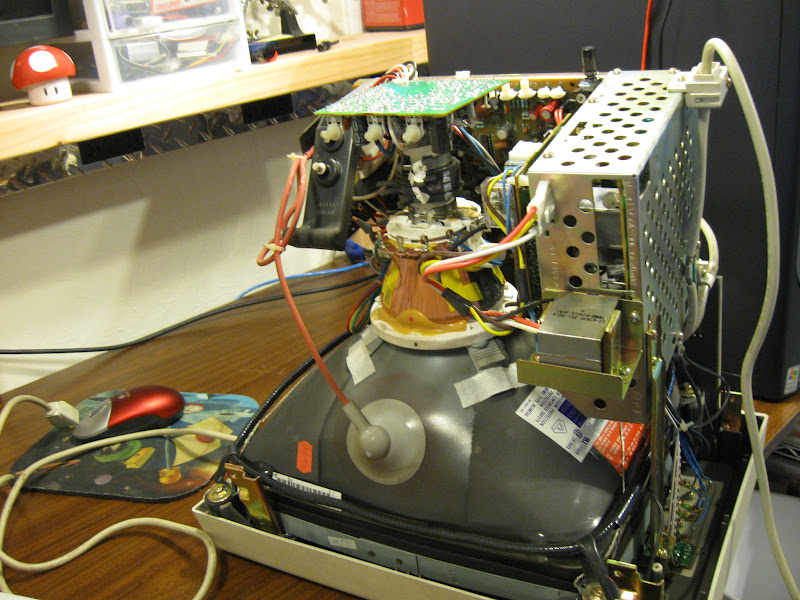
I got my hands on an old SYSDyne CD 1314 monitor (January 1987), but alas it does not work. I plug it in and hit the power button and nothing happens, it remains dead.

There is a switch on the back and a touch sensor on the front to turn it on, but neither do anything.

So I need the service manual or any suggestions on where to start looking to repair this thing.
 
So I opened it up and looked around. There is nothing obviously wrong that I can see. The caps look good and the inside is mostly clean and dust free it looks pristine inside.

The high voltage side is inside a metal cage that I cannot seem to work out how to get into it, so I can't find any fuses to test.

The only clue I have is that there is a transformer with about 5 wires coming off it that gets really hot when the unit it plugged in and turned on.

Only numbers on it are:
Code:
E2-41BTF-SS1-0018
TRNS-POWER-3051
A
LOT NO 7511

Google does not help when I try to search for a repair manual or the transformer numbers.

Any ideas?
 
Sounds like a possible power supply problem which means you'll need to get inside the metal cage.
As you mentioned ....first check for blown fuses. Then look for burned/black components or leaky/bulging
capacitors. Does the monitor have a power indicator light ?

The REAL high voltage you need to be aware of is the large red lead running to the suction cup looking
thing on the CRT. Stay away from that wire. Typically around 25,000 volts and can retain a charge
for some time, even after the monitor is powered off.
 
I think I had one of these monitors at one point, or at least one like it. Are you sure this is a color monitor? The one I had was monochrome. Looking at it from the back, is there a bracket on the left containing the transformer, a small power board, and such?

In mine, the actual monitor part ran off 15vDC, generated by the power supply that was seperate from the monitor's PCB itself.

Do you have a picture of the inside of the monitor?

-Ian

From the research I have done I am about 90% sure this is a CGA monitor. I do have a picture of the inside that I will post later this evening, but your description sounds close. There are indicator lights on the front, but they do not light up at all.

@Mikey99 - Thanks for the warning, I am aware of the dangers of working inside a CRT. I do not see any indications of leaking or bulging caps. The inside looks very clean, there is very little dust as well.

I will have to do my best to see about getting into the high voltage cage I mentioned, its not going to be easy, but we'll see.
 
Last edited:
Here are two pictures I took.

The monitor is lying on it's screen, the first one is from the side (would be the left if you were looking at it from the back) and the other is from the top of the monitor.

IMG_0362.JPG


IMG_0361.JPG


The transformer you see there attached to the metal cage gets really hot when the monitor is plugged in. After about 5 minutes you can barely touch it, and it take quite a while to cool down.
Also, and little tip from an old tech: If that monitor has ben setting up for a long period of time, check the fly-back transformer and the yoke on the neck of the CRT.
 
Last edited:
It might be normal that the transformer gets that hot...probably why they mounted it near the top
like that so it can ventilate through the vent holes in the top of the case. From what I can tell thats probably
the main power transformer, takes 120 VAC input and drops down to a lower voltage for the power
supply. You would need to trace the wiring from the power cord and see if it runs to that transformer.
If the transformer is getting warm when you turn on the monitor , at least you know the power switch is good.

Its possible an electrolytic capacitor could be bad and not be leaking or bulging. I've repaired several IBM
EGA monitors by just replacing all the electrolytic capacitors in the PS. Bad capacitors in these monitors
can cause lots of bizarre symptoms, and waste lots of time troubleshooting. The IBM EGA also has the power supply
in a metal cage like that and they always ran hot which caused the capacitors to overheat and go bad.
They only used 85 C temp rated capacitors.... I always replace with 105C rated.

For now just get that cage opened up and post some pictures of the inside.
 
IMG_0365.JPG


The two fuses (both look good, and test good with the continuity checker on my meter)

IMG_0364.JPG


IMG_0369.JPG


I am not sure, but the only cap that looks like it *might* have a slight bulge on the top is this one:

IMG_0368.JPG


Other than that it continues to look clean inside, no bulging caps, not leaking, no fuses blown etc. The connector to the top left in the picture has 110v AC coming out on it on the yellow and brown wires.

The other two caps:

IMG_0367.JPG
 
That is a very clean monitor ! doesn't look like it was used much. Whats on the other circuit
board right next to the metal cage in the first two pictures you posted. Looks like a relay
and some other power supply components.....

Also, those two gray resistors, the one on the left , 8.2K looks a bit dark on one end...
like maybe it overheated.
 
Last edited:
Also, those two gray resistors, the one on the left , 8.2K looks a bit dark on one end...
like maybe it overheated.

Nah, just a trick of the light, both those resistors check out with the meter. The 8.2k measures at 8.35k, and the 6.8k measures out at 6.9k.

IMG_0373.JPG


IMG_0374.JPG


The 4 blue cables on the right (on the plug) go to the buttons on the front of the monitor, as does the green wire on the bottom there. Basically your finger grounds the appropriate blue wire to set that function (Mode, Brightness +, Brightness - and Power).

Here is a close up of the relay:

IMG_0377.JPG
 
Last edited:
Hmm, seeing as how its totally dead the problem is most likely in the main power supply in the cage.
You could try checking the diodes on the PS circuit board with an ohmmeter. In most cases you can
get an idea if they're okay checking them in circuit. Should read high resistance in one direction,
then flip the leads and should read low resistance in the opposite direction. I wouldn't expect that any
of the diodes were shorted or it would be blowing a fuse. Could have an open diode though.

Did you by any chance notice if that Omron relay clicked when you turned the power switch on ?
 
Did you by any chance notice if that Omron relay clicked when you turned the power switch on ?

When the switch on the back is pushed in nothing happens, when the switch on the front is touched also nothing happens. No click from the relay. How does on test a relay?

EDIT: all the diodes give me resistance, that differs depending on the direction of the meter, so I think that means they are all working right?
 
Last edited:
Hmm, whats the deal with the switch on the back ? Is that a power switch too ?
I've never seen a monitor with the power switch in the back . Is there anything
printed on the case to indicate what that switch function is ?
 
Hmm, whats the deal with the switch on the back ? Is that a power switch too ?
I've never seen a monitor with the power switch in the back . Is there anything
printed on the case to indicate what that switch function is ?

Actually now that you mention it, no it does not. It has a diagram that shows you the on and off positions but that is it. I just assumed it was a master power, and the one on the front was a soft power switch (ie controls the logic and the relay).

There are two red wires that come from the switch on the back, and they run into this cage. You can see them on the picture of the first fuse (the two on the right). Also it works, there is continuity when it is in the on position and none when it is in the off position.

EDIT: Here is a picture of the front of the monitor:

sysdyne-cd-1343.jpg
 
Last edited:
Yeah, sounds like the diodes are probably okay. A schematic would certainly help
to trace the voltages. On the main PS, where does that other connector with black
white green blue go to ? It looks like thats probably the lower DC voltage outputs
that feed to the other parts of the monitor. You could test to see if any DC voltage
is coming from those pins when powered on.
 
Last edited:
On the main PS, where does that other connector with black
white green blue go to ?

They run to the other PCB under the tube. There is a voltage coming off of them. Without knowing which is ground it is hard to get an exact voltage, but I can read somewhere around 2v.

Also, the 110v coming from the connector on top left of the cage measures at 110v AC and it runs straight to the relay. But it would seem that when the relay is power up with 110v it does nothing, no click or anything. Should the engage when power is supplied to it on the right side (as per the picture above), so could it be the relay, or am I thinking about it backwards (ie 12v turns on the 110v)?
 
IMG_0378.JPG


This is the transformer. If you look at the first picture above that shows the cage open, you will notice a black wire that runs down and out on the right. This is the black cable seen on the transformer above.

The red wire on the transformer comes from the red wire on the connector on the top right of the open cage picture and the white wire comes from the orange one (the two outer wires). The two inner wires run straight to the high voltage side of the relay (the yellow and brown wires seen at the top of the picture above).

Okay. I get 110v AC on the relay wires. I get 110v AC on the black and white wires (seen above), but 0V on the black and red or white and red.

Now there are two blue wires coming from the transformer on the board with the relay, they can be seen on the bottom right hand corner of the relay board. I assume these are the outputs for the transformer. I get about 2V DC from this pair. I am guessing that I should be getting around 12v from them, though I have no way of being certain. Do you guys think this transformer might be to blame? How can I look it up and verify this?
 
The output of the transformer will be AC voltage..... so check the blue wires again with your meter set on AC...
probably should be 12 volts AC or higher.

Also, on the other connector with black white green blue , these should be DC voltages, and I would expect
around 5 or 12 volts DC. But it nots clear which wires to measure between. Its possible the black is a ground
and each of the other wires is a different voltage. Or the black/white is one voltage pair and the green/blue
is another.
 
Last edited:
Back
Top