• Please review our updated Terms and Rules here

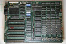
Looking for blueprints or a technical drawing of a motherboard.

Fire-Flare

Experienced Member
Joined
Dec 17, 2009
Messages
273
Location
Washington State
What I need are the screw hole distances and keyboard/cassette port placements so I can mount an ITX motherboard in my 5150 chassis.

My searches have come up empty, any assistance you guys can provide will be greatly appreciated.
 
The first thing you'll need is a saw. :) The 5-slot motherboards (5150) have a different spacing between the slots, so an 8-slot (XT or later) board doesn't line up with the card slots in the case. Drop your board in and you'll see what I mean. If you still want to try, PM me and I'll measure one of mine tomorrow. Or just use an IBM XT case bottom, the tops are the same except for the little silver ID plate. One of my 5150s has an XT top on it.
 
It's been too long... was it possible on the original IBM cases to unscrew and remove the expansion card guides? I remember at least having an XT-styled clone case where you could. IF that's possible I'm pretty sure you could fit a mini-ITX board so the ATX-style port area would be accessible through the gap. (You could of course saw out the area if it doesn't unscrew, at risk of being labeled a Philistine.)

The one thing that might be a problem, depending on board layout, is the part of the drive bays the overhangs the motherboard area. It's darn low and may well interfere with a DIMM socket or heat sink.

Allow me to clarify: The project is to mount an ITX board where the original was without altering the chassis. The board will be toward the front of the case with outputs routed to PCI brackets and the keyboard pins soldered to a DIN socket installed on the adapter. I have a second for the cassette port but I don't know what to do with it.

I don't believe I'll be using any actual expansion cards, but I have a flexible PCI riser so lining up the boards single expansion slot won't be an issue.
 
Allow me to clarify: The project is to mount an ITX board where the original was without altering the chassis...

Aaaah, so you're aiming for a total stealth job. Easy enough.

Do you have the 5150 case in front of you? The standard dimensions of a Mini-ITX board are 17x17cm, or a little under seven inches square. If you don't have the ITX motherboard yet I'd suggest cutting a piece of cardboard to the same size and test fitting it in various places to see if there's anywhere it can nest without being overhung by the disk drive bays. Those are going to be your biggest problem. I think you just *might* be able to fit it without overlap in the upper left hand corner of the case (looking down from the top with the case open) while leaving enough room between the I/O ports and the slots to run the cable extenders to your slotted ports. If your particular ITX board has a tall heat sink or a DIMM socket in the lower right hand corner even without overlap you might not be able to use a full-depth device in the left drive bay, however. (Are you planning on trying to retain a floppy drive in this machine? It may be hard to find an ITX board that still has a floppy controller.) If you have 7 inches between the backplate and the drive bay support but not enough extra to route cables maybe you could put the board sideways with the ports either facing out to the side or into the power supply area. If you're using extenders anyway there's no reason the board needs to be placed in any particular orientation.

Are you planning to drill holes in the 5150 case for threaded standoffs to mount the ITX board on? If you want to leave the case completely unmolested you could probably get away with mounting the ITX board on a small piece of sheet metal and then just sticking that inside the 5150 with some double-sided carpet tape. (Or some similar expedient.) You could likewise anchor your keyboard/cassette port DINs in a similar way, although I seem to recall that one of the threaded supports for the original motherboard was located in that area. If that's the case mount the DINs to a small piece of perfboard with a hole drilled to line up with the original mounting post. Heck, hypothetically at least you could even take a piece of steel or Plexiglas, cut it to the same dimensions as the original motherboard, drill it in the same places for screws and standoffs, and mount the motherboard and DIN plugs to it so it pops in and out as one module.
 
Aaaah, so you're aiming for a total stealth job.

If you're using extenders there's no reason the board needs to be placed in any particular orientation.

Heck, hypothetically at least you could even take a piece of steel or Plexiglas, cut it to the same dimensions as the original motherboard, drill it in the same places for screws and standoffs, and mount the motherboard and DIN plugs to it so it pops in and out as one module.

That's the configuration I'm aiming for, using the original mounts to properly secure an adapter for the ITX. And placing short 5.25 devices in the left-hand bays.

I've already confirmed an area where the ITX and its cables will be happy and I have a sturdy piece of material to drill. The only thing left to do is get the precise locations to drill. I'd measure the standoff points, but I don't trust myself to do that right.
 
Do you have the original motherboard? If you do you could just lay it on top of your material and use it as a template.

If not... someone that does will probably have to help you measure it out. The plastic standoffs do allow some wiggle room, so if you were to stuff some standoffs into the case slots, lay a piece of thin cardboard over them all, and deduce where they touch it by feel you could probably get "close enough". (Maybe stick a sharp nail or a thumbtack in each standoff slot and press your cardboard template down so the tacks mark the hole locations?)
 
Out of interest, what PSU are you intenting to use?

If you have the 5150 original I guess a simple external 12v job would easily fit inside (with the original board removed of course) and easy to hook up to original switch and AC outlet for monitor - the fan in there is mains powered too. Then use a picoPSU on the board itself, it it needs it?

If you can wait till later I'll post up measurements from a 5150 board.
 
Out of interest, what PSU are you intenting to use?

If you have the 5150 original I guess a simple external 12v job would easily fit inside (with the original board removed of course) and easy to hook up to original switch and AC outlet for monitor - the fan in there is mains powered too. Then use a picoPSU on the board itself, it it needs it?

Back in the day I used to hot-rod 5160s with Baby AT 486/Pentium motherboards. (They'll fit if you're not picky about every standoff matching up and you're willing to take tin snips to the drive bay. Yes it's blasphemy now but it wasn't in the mid-1990's.) Anyway, for power in at least one instance I gutted the case of a 63 watt 5150 power supply (At one point I bought a couple complete 5150s for $10 from government surplus and used the disk drives on my TRS-80 Model I, so I had the parts lying around) and stuffed it with the contents of one of those 200 watt Baby AT-tower form factor supplies. Those supplies were about the same dimensions as ATX so it should be pretty easy to find a supply who's innards would fit. Not that stuffing it with a simple 12v wall wart and one of those picoPSUs is a bad idea either. It'd be quieter.

The one issue is what to do with the lovely *kerthump* rocker power switch. ATX soft power calls for momentary contact switches, which you could do with a small pushbutton on the back or something, but it'd be a shame to not be able to use the giant lever somehow.
 
Out of interest, what PSU are you intenting to use?

If you have the 5150 original I guess a simple external 12v job would easily fit inside (with the original board removed of course) and easy to hook up to original switch and AC outlet for monitor - the fan in there is mains powered too. Then use a picoPSU on the board itself, it it needs it?

If you can wait till later I'll post up measurements from a 5150 board.
I have a no-name PSU and a 90 watt pico. I intend to remove the inner walls and wire them together to complete the stock appearance and functionality.

I would greatly appreciate your assistance with the measurements.
 
Those supplies were about the same dimensions as ATX so it should be pretty easy to find a supply who's innards would fit. Not that stuffing it with a simple 12v wall wart and one of those picoPSUs is a bad idea either. It'd be quieter.

The one issue is what to do with the lovely *kerthump* rocker power switch. ATX soft power calls for momentary contact switches, which you could do with a small pushbutton on the back or something, but it'd be a shame to not be able to use the giant lever somehow.
Grounding the lead wire will take care of that, and APCI in operating systems can be disabled.

Alternatively, since the machine will be used mainly as a backup server, I could use the switch to power off the backup drive(s) to conserve energy and install a Lian-Li BZ-U01B in one of the 5.25 slots. (I'm amazed nobody else makes 5.25 devices with power and reset buttons)
 
I don't suppose you'll be freeing up either an original drive bay blank or an FDD from this machine?
 
I don't suppose you'll be freeing up either an original drive bay blank or an FDD from this machine?
I assume the 'blank' would be full height, right? The only blank in there when I picked it up was installed over the half-height floppy drive and neither are stamped.
 
Back
Top