• Please review our updated Terms and Rules here

PC6300 no longer POSTs

NeXT

Veteran Member
Joined
Oct 22, 2008
Messages
8,144
Location
Kamloops, BC, Canada
I had my AT&T PC6300 working and booting before I put in storage last October. It was a fully punctioning system.
Before I put the system away I double checked that the battery was good. It was reading 2.8v and showed no signs of leaks. The drive was then parked and put away for storage on its side (drives closest to the floor).
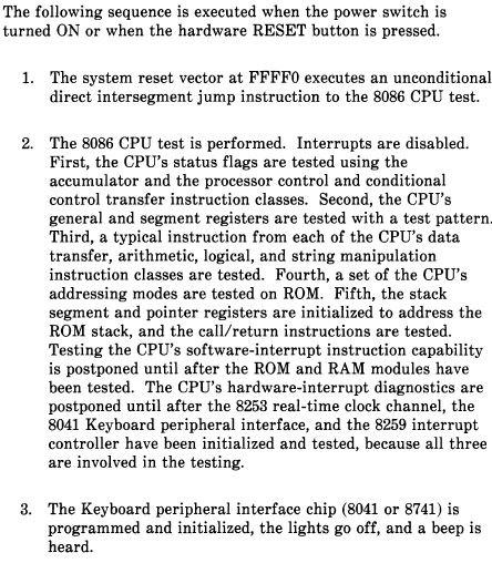
I pulled it out the other day and tried to boot it and knew something was wrong. When you power on a 6300 the keyboard LEDs will go from solid to flickering, then they will go out and the system will show something on the screen (POST data). This time however the lamps remained solid and nothing else happened.
I opened the system and discovered that in five months the battery had gone dead and leaked. There wasn't any visible trace damage but the area around C10 to C0 (board is arranged into a grid) all showed light signs of corrosion. I pulled the system apart, cleaned the pins on socketed chips and edge connectors, washed the mainboard and left it to dry over a heating register and cleaned the video card. In the process I found the corrosion had gummed up the reset button and it was stuck on. Some contact cleaner and TLC fixed it.
After letting the boards dry (completely) I reassembled the system and tried again with my POST card installed.
The POST card constantly reported FF (wrong because that means the ssytem is booting) but had the right voltages and blinked the CLOCK light (and in turn the keyboard controller started flickering the LEDs again so that was working again too) but otherwise nothing else happened. It's now showing the same symptoms I saw on my Olivetti M24: Power is fine and visually it's okay even though the battery had leaked however it was otherwise doing nothing else (though in this case I actually had a keyboard and monitor).
Components that show corrosion on their pins are a 0N74LS08N, two M5M4256P memory chips soldered to the board, two socketed MB8264A-15 memory chips, and a diode. Other damaged parts include the power LED no longer works (but receives +5v) and the speaker got hit pretty hard (no clue if it's still any good and if I'm missing a error beep or something)
I can't confirm if the monitor is getting power. This particular monitor never gave any high voltage squeal when it was on though visually it was working.
 
Odd--I've liked the 6300 setup because the battery is normally upside-down, so you'd think that any goo would just drop onto the bottom cover plate. Guess not. On the other hand, I've had the speaker drop off its sticky tape and break its leads--I just replaced it with a small piezo unit.

Does the flickering stop? If so, I'd hook up another speaker to see if it's trying to tell you something.
 
Flickering never stops. It should though as the POST tests progresses. The flickering however isn't because the BIOS is testing the keyboard controller I think. It's probably the clock signal. You can have the EPROMs removed and it will still do that so I assume it stops because the BIOS is chattering to the keyboard controller.
I attached another PC speaker and got not a chirp out of the thing.

Like I said, the only reason I got battery damage was because I stored the system on its side. If I had known this was going to happen it would of been stored the regular way.
 
Let me guess--you stored it so that the battery was on the highest end? :facepalm: I'd probably start by taking the mobo out and inspecting traces under each IC where the electrolyte leaked, even if it means removing the IC.

Do you need a schematic?

Lotsa fun...
 
Stop reading my mind. I facepalmed too when I realized who unwise my decision was but like I said, I swear that battery was fine before I stored it. If it was the other way around it would of dropped right off the board. I got no schematics but chip removal should be okay after I borrow my friends reflow station.
 
Got the chips desoldered and removed. Same with the speaker. Corrosion was cleaned and there was no damaged traces. The speaker fell apart though from a lot of corrosion.
Soldered the components back down and the problem persists. :(
All I know for absolute certain that there is a clock signal. I can't say what else might be wrong.
 
NecroBUMP.
I've come back to this machine again.
To catch anyone up with my situation The machine was working when placed in storage. Several months later it was taken out of storage and found that the battery had leaked and dripped down the front 2" of the mainboard. The machine now no longer POSTs. The PCB is visually undamaged from the leak but the power LED has died and the speaker has been ruined. Both have now been replaced. Corrosion was found on two sockets in ram bank 1 and were replaced with new ones. Several chips were desoldered so I could inspect for damage under them and found nothing. I reinstalled the chips with sockets.
I have two POST cards, one tells me voltages, clock presence and a two digit POST code. The other card displays DMA, interrupts and two digit POST codes as well. +5 and +12 are good, a clock is present however only one card reports a FE code (or 00, or FF randomly when you turn the power on) and the other reports nothing. After a period the INT15 lamp will come on and if left for a long period you will get DMA 7 lit as well. The keyboard controller and POST cards respond to the reset button so that isn't stuck.

6300t.png

Looking at part of the service manual I can tell that we are not reaching step 3 and I can't tell where in step 2 we might be hanging, if we're even reaching step 2 at all. I do now have a logic analyzer but in this case I am unsure what I should be looking for or at.

Edited: As a sanity check, I compared my EPROMs to Chuck(G)'s image files and they are okay so the BIOS is not corrupted either.
 
Last edited:
I have two POST cards, one tells me voltages, clock presence and a two digit POST code. The other card displays DMA, interrupts and two digit POST codes as well. +5 and +12 are good, a clock is present however only one card reports a FE code (or 00, or FF randomly when you turn the power on) and the other reports nothing.
I cannot find anything that indicates that PC6300 machines output POST codes.
 
I do now have a logic analyzer but in this case I am unsure what I should be looking for or at.
At reset, the CPU jumps to address FFFF0, which is an address near the end of the BIOS ROM range.
So what you could do is see if the Chip Select line on each of the two BIOS ROMs is being activated.

If not seen, the problem cause is a very low one.
If seen, then maybe try an odd/even pair of Supersoft/Landmark diagnostic ROMs.
 
If seen, then maybe try an odd/even pair of Supersoft/Landmark diagnostic ROMs.
Chip Enable lines are high. I see activity on the Output Enable lines or any of the address lines.
Will the Diagnostic ROMs work in the 6300? I thought those were for the IBM's and their similar clones? The 6300 doesn't even use an AT form factor board.

I cannot find anything that indicates that PC6300 machines output POST codes.
Ah, okay. I was going out on a whim because I saw the M24 had several codes, mind you none of them would be all that useful here.

Progress edit: I'm now fairly certain that we are getting stuck in some sort of loop in Step 2. Watching the RESET and READY lines on the 8086 I can see when the CPU responds to the reset switch and when it begins doing something with the EPROM. This can be confirmed by removing the EPROMs and observing the CPU remaining in a ready state after a reset. To further minimize my system configuration I have removed ram bank 1 and set the dip switches accordingly so now we only have the 512k that is soldered to the board.
 
Last edited:
I was going out on a whim because I saw the M24 had several codes, mind you none of them would be all that useful here.
You are right. I had forgotten that the PC6300 and M24 share the same BIOS code.
The web page [here] shows seven codes for the M24.

Will the Diagnostic ROMs work in the 6300? I thought those were for the IBM's and their similar clones?
Although described as a PC clone, speaking from a hardware perspective, the PC6300 is significantly different from the IBM PC. I don't have one (or an M24) myself. I know that a few VCF members have a PC6300/M24, so maybe they will comment.
It's possible that there is enough video hardware compatibility for the Supersoft/Landmark ROMs to at least display something on-screen. Suitable ROMs (odd/even) using the PC version of the diagnostics would need to be created.

Chip Enable lines are high. I see activity on the Output Enable lines or any of the address lines.
The PC6300 uses two 2764 type ROMs, i.e. active-low Chip Enable and Output Enable lines.
Both lines have to be low for the ROM to output data.
If the Chip Enable is always high, there will never be any output from the ROM. Are you sure you measured the right pin?
 
Although described as a PC clone, speaking from a hardware perspective, the PC6300 is significantly different from the IBM PC. I don't have one (or an M24) myself. I know that a few VCF members have a PC6300/M24, so maybe they will comment.
It's possible that there is enough video hardware compatibility for the Supersoft/Landmark ROMs to at least display something on-screen. Suitable ROMs (odd/even) using the PC version of the diagnostics would need to be created.

Nothing you can do about burning your own EPROMs, but as far as I can tell (without owning one), the M24 uses a CGA-like mode, and can run Flight Simulator unmodified... so it should work.
 
Last edited:
The PC6300 uses two 2764 type ROMs, i.e. active-low Chip Enable and Output Enable lines.
Both lines have to be low for the ROM to output data.
If the Chip Enable is always high, there will never be any output from the ROM. Are you sure you measured the right pin?

In short, no.
All I could do was pull up the chip spec and find a pin. If you say they have to be low then no, they never go low. They remain high. (this assumes we're talking positive logic right now, otherwise they're always low)
 
Chip enable might be driven from an identity comparator like 74LS520, 521, 688... follow it back and hopefully you'll find something socketed :)
 
If you say they have to be low then no, they never go low. They remain high. (this assumes we're talking positive logic right now, otherwise they're always low)
In my many years of electronics experience, 'low' always corresponds to the lower of the voltage range for the logic used (TTL, CMOS, etc.), and 'high' always corresponds to the higher of the voltage range.

However, whether 'active' is high or low depends on whether a signal is 'active high' or 'active low'.
Active high: If the signal is named, for example, TRIGGER_1, then a trigger happens (activates) when the signal goes high.
Active low: If the signal is named, for example, TRIGGER_2, then a trigger happens (activates) when the signal goes low.

All I could do was pull up the chip spec and find a pin
Another 2764 spec is [here] and it shows that:
* Both the CHIP ENABLE and OUTPUT ENABLE pins are active low - to be driven low to accomplish their function.
* Page 2 explains how both of those pins need to be low for a 'read' operation.

Motherboard designers do different things. So on one motherboard type, the OUTPUT ENABLE might be tied permanently low, and the CHIP ENABLE line gated low by the ROM decode logic. I've seen the opposite done - CHIP ENABLE tied permanently low, and the OUTPUT ENABLE line gated low by the ROM decode logic. Or it could be that both lines get gated low.
The circuit diagram will show you how it is being done in the PC6300.
 
I cannot find anything that indicates that PC6300 machines output POST codes.
What about replacing the BIOS with one that does? I wrote my "own" BIOS by taking parts of other BIOSes (including the Anonymous one) and inserting my own POST codes. At this moment I use the address 80h and a self built card with two intelligent 7 segment display. But having the source code, I could use the address of a LPT port. Sources are free, assemble with NASM.
 
Although described as a PC clone, speaking from a hardware perspective, the PC6300 is significantly different from the IBM PC. I don't have one (or an M24) myself. I know that a few VCF members have a PC6300/M24, so maybe they will comment.
It's possible that there is enough video hardware compatibility for the Supersoft/Landmark ROMs to at least display something on-screen. Suitable ROMs (odd/even) using the PC version of the diagnostics would need to be created.

First off, OP should grab the 6300 Service Manual: https://docs.google.com/viewer?a=v&...xhdHQ2MzAwc2hyaW5lfGd4OjJjMTRiYmM3MTAwZjY1NjA
(to download, click the arrow to the right of the filename on https://sites.google.com/site/att6300shrine/Home/downloads )

Secondly, the 6300 is indeed very different and if anything in the supersoft/landmark ROMs relies on something specific to the 8088 (like the prefetch queue size), or something speed-related (xtal is 24MHz, CPU runs at 8MHz), then the diag roms won't work. I suppose it doesn't hurt to try, but my fear is that the differences in architecture will result in false positives.
 
What about replacing the BIOS with one that does? I wrote my "own" BIOS by taking parts of other BIOSes (including the Anonymous one) and inserting my own POST codes. At this moment I use the address 80h and a self built card with two intelligent 7 segment display. But having the source code, I could use the address of a LPT port. Sources are free, assemble with NASM.
Per earlier posts, it was identified that the supplied BIOS in a PC6300/M24 does output some POST codes.

Secondly, the 6300 is indeed very different and if anything in the supersoft/landmark ROMs relies on something specific to the 8088 (like the prefetch queue size), or something speed-related (xtal is 24MHz, CPU runs at 8MHz), then the diag roms won't work. I suppose it doesn't hurt to try, but my fear is that the differences in architecture will result in false positives.

NeXT is in that situation of having what appears to be a 'dead' motherboard, and having done the basics (reseat chips, etc.) to try to get it going. In such cases involving an IBM 5150 motherboard, running the SuperSoft/Landmark diagnostics is a good next step because the first thing the diagnostic does (before any tests) is initialise video and display something on-screen. If a display is seen at all, it tells a lot about the state of the motherboard (i.e. it is basically running). And that was the basis for my suggestion to NeXT to try running the SuperSoft/Landmark diagnostics.

But as we know now, the ROM sockets are not getting the required signals to read data from fitted ROMS, and so fitting SuperSoft/Landmark diagnostic ROMs, the standard PC6300 BIOS ROMs, custom ROMs, whatever, is not going to achieve anything.
 
Back
Top