• Please review our updated Terms and Rules here

Help fixing a Commodore PC-10 III

Timo W.

Veteran Member
Joined
Nov 25, 2014
Messages
2,154
Location
Germany
Got a Commodore PC-10 III lately (a PC-20 III actually), which is in quite bad condition. Sadly, it also doesn't work at all. When switching it on, everything behaves normal (fan is running, power led goes on), but the system just doesn't come up. No beep, no video signal, nothing. The mainboard seems to be completely dead. Now I have disassembled everything and have the most basic setup (psu + mainboard). I reseated all chips, tried a different cpu, replaced a cap that was looking quite worn... Still, nothing. I can rule out the psu, as all voltages are fine.

One odd thing I noticed is that the reset switch has about 500 ohms in normal state. Is that correct? I would expect it to have 0 ohms in normal state and goes open when pressed (the latter it does, at least).

What should I check next? Anyone got the schematics?
 
I have two Commodore PCs. One is PC20-III and the other is PC20-II. I also had a second PC20-III but motherboard there was dead too. You will need an oscilloscope if you seriously want to hunt the cause. I wanted to give you manual but SkydivinGirl was faster. And I got it work with 3.5" hd floppies and CF card as hard drive.

Lastly I have written RTC DOS utility that works correctly with on board RTC chip even in 21st century :satisfie:
 
I never finished mine (same symptoms), but some things that helped find faults (I confirmed the faults, but didn't finish the repair) were a copy of the Supersoft/Landmark Diagnostics ROM written to an EPROM - this showed me issues with memory which seemed almost random (in your case you might be lucky to find it's a single RAM chip in the first bank) - and then an oscilliscope - watching the RAS signal on the first two banks I could see it was not firing at all - then I worked upstream with the diagram and found a 74LS chip where a 74S was supposed to be and had unsurprisingly burnt out with age.

Scope I used cost me $5 from a local rubbish dump and is 30+ years old, good enough to show obvious problems.

The big pain in the ass was working with the old tiny solder joins, as a result I broke a few traces, and haven't got around to sorting it properly. I have a good RAS signal now, but broke something else (damn it).

Something small to check, is while the machine is running, check +5V is close to 5V (between 4.8 and 5.2).
Reset switch should show 0 ohms when closed, and no connection when open, the terminals on the motherboard might be 500 ohms themselves though (so the switch shows 500 when it's plugged in).
 
Last edited:
I was planning on doing the same thing! I'd appreciate it if you could share yours. I made a fancy batch file to overcome the RTC issues. :)

Oh interesting!
I'm interested in that too... also the source code if you please.
I used to have a PC10-III as my first PC, back in the late 80s, and recently bought a PC20-III, which I have restored to working condition, and kitted out with a VGA card. The original HDD even works still :)
 
Thanks for the answers.

I have a PC10-III as well. Not sure what else you can try, but here's a link to the manual with a schematic.

http://dostalgie.de/downloads/pc10II...DORE_EN_DE.pdf
Great, thanks. :)

Something small to check, is while the machine is running, check +5V is close to 5V (between 4.8 and 5.2).
Reset switch should show 0 ohms when closed, and no connection when open, the terminals on the motherboard might be 500 ohms themselves though (so the switch shows 500 when it's plugged in).
Checked the voltages at the very beginning, they are all fine. Both +5V Power Good and +5V VCC measure exactly 5.0V. +12V measures 11.8V, which is within tolerance, too.

Since the system simply does nothing at all, I suspect it's probably stuck in a reset loop (that's why I checked the reset switch). Unfortunately, I don't have a scope (yet).
 
You can check the RESET line with a multimeter or logic probe. You don't need an oscilloscope. Just make sure to use a high-impedance multimeter (VTVM or DMM) to ensure that don't pull the line by measuring it (shouldn't anyway).

I find a logic probe very useful for these kind of diagnostics. You can readily check the clock, tell if the CPU is stuck in a loop in a certain area of address spacel, et cetera, without the expense and hassle of using a scope.
 
The following URL has a good information on the Pin configuration of the CPU (8088) and which Control Lines (Signals) are active HIGH or LOW.
http://nick-black.com/dankwiki/images/1/16/8088_datasheet.pdf

I'd suggest double checking the Power Supply Voltage at the CPU being within 1% of the what's shown on the Schematics. If that is good, proceed
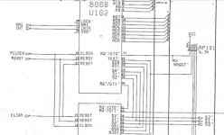
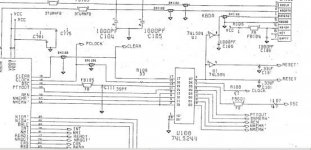
to check for a good CLOCK Signal. Then VERIFY all the Control Lines for the CPU (RESET, INT, NMI, READY, CLEAR, TEST (active LOW)) for
all that are used on your system according to the Schematic.

com1.jpgcom2.jpg

If those Control Signals are correct you can VERIFY all the Address Lines by using the NOP (0x90) Instruction by the CPU to step through all possible
Addresses in a loop. This allows you to follow all address lines through all IC's on the Motherboard.

To do this, you need a CPU with the DATA Pins Bent out a bit so they don't fit into the Motherboard. Strap the D0-D7 Pins to create 0x90 on the Pins.
Re-insert the Test CPU and verify ALL Address Lines. (You could also use a SPARE 40 Pin IC Socket, and by using small 30 AWG Wirewrap wire
create a TEST Socket with the Data Lines bent out and Strapped for 0x90. Just make sure none of the D0-D7 Pins on the TEST IC Socket make
contact with the Motherboard.)

The only thing left would be the Data Lines, and that will require a In Circuit Emulator (ICE) or CPU Exerciser built from an Arduino Mega.

Keep us informed as to what you find.

Larry
 
Then VERIFY all the Control Lines for the CPU (RESET, INT, NMI, READY, CLEAR, TEST (active LOW)) for
all that are used on your system according to the Schematic.
RESET seems fine. It's +5V when turning power on or pressing the reset switch and goes down to 0V after a second. READY, however, has 3.2V..?
 
If anyone is interested in the batch file I made for 'fixing' the RTC issue, you can see my whole PC10-III build on AmiBay:

http://www.amibay.com/showthread.php?64820-My-Commodore-PC10-III-Project

I'm still having trouble with the RTC. It's supposed to keep time with as little as to 2V but the computer doesn't even detect it without at least 4V - 5V. I have a newer RTC that is compatible that I'm going to try since I've already checked the rest of the RTC circuit and couldn't find issues.

Good luck on troubleshooting!

Heather
 
Nice Heather. I was fortunate enough to have removed battery soon enough, before any damage has been made. My RTC chip works reliably. I too have Sergey's VGA but did not test it in Commodore PC. This card has some compatibility problems, so I replaced the smd chip 3x before I realized it might be working in another PC. In my Taiwanese XT clone no luck .. I suppose it would work in Commodore PC, but had no motivation anymore. Now I am using PC10-III with on board CGA and green phosphor monitor, that's how I like it most. I even patched the BIOS, so that it does not complain about default floppy drive not being installed, as I have my floppies on secondary channel - connected to multi IO ISA card.

Good luck Timo!
 
Timo,
As far as the 8088 is concerned, the MIN Input High Voltage is 2 Volts, so the 3.2 will be seen as a High, even though it might be a Tri-State Output
of the FE2010 PLCC. So, I wouldn't get hung up on the 3.2 Volts for READY. If you verify some of the other OUTPUT Signals of the PLCC
like NRQGT PIn 24, it likely also is 3.2 volts.

On RESET, do you see any of the Address Lines toggling HIGH to LOW? Do they continue to toggle, or do they stop in one state?

Larry
 
Is that supposed to work with the PC-10 III?
As per my post on page 1, I used this to identify I had a memory problem on my PC-10, which lead me to failed 74LSxx chip.
But I needed to slot in my own MDA card - because Lansoft wont start up the video expansion ROM on the Commodore.

It's certianly not the only way to do this, I just find it handy because if it starts, you can know large chunks of the machine are in working order, and if there is a failure you can get some hints as to where to look.
 
Last edited:
As per my post on page 1, I used this to identify I had a memory problem on my PC-10, which lead me to failed 74LSxx chip.
But I needed to slot in my own MDA card - because Lansoft wont start up the video expansion ROM on the Commodore.
That's what my question was aimed at. So it won't work on a stock PC-10 III unless you add an extra video card.

I will measure the address lines later, as suggested by ldkraemer. Can I use a POST card in the PC-10 III? I remember reading that they normally don't work in XT class machines, as the POST code is either sent to a different port or not sent at all.
 
Back
Top