mrmanse
Member
Hi!
I have an IBM 5160 with the 64-256k motherboard and the 11/08/82 BIOS.
Original BIOS ROMs are labeled U18=1501512, U19=6359116.
I wish to upgrade BIOS to the 05/09/86 version, but I don't own a programmer so I asked for help in a facebook group and a kind person helped me out.
So I got the files in BIOS_5160_09MAY86.zip from minuszerodegrees programmed into 2 identical Nec D27C256D-25 EPROMS, but unfortunately they don't work With them installed the motherboard is dead, no beeps, monitor is powered down (LCD on VGA-card), and no blinking lights on the keyboard (i use a model M with AT/XT protocol support that blinks while detecting the XT protocol).
So I asked the guy if he's sure about the programming, if he verified the writes, and such, and he is sure they are correct. I have no reason to doubt him, but if course, I can't verify the EPROMS myself.
* Could it be a problem with the C in choosing 27c256? I read that they need 6V, do I have that? Should I check anything with multimeter?
* Or are they to slow? -25 ? I read somewhere that -20 is required.
* Could it be that the 16-bit VGA-card I'm using only accepts the 11/08/82 BIOS?
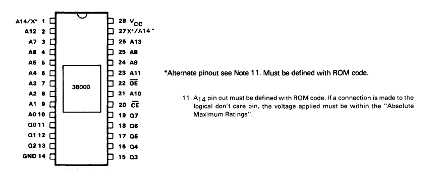
* I also read on one site that shorting pin 1 and 28 is needed, but that was not for the IBM XT.
I can return the EPROMS and ask for them to be verified again, but I'd like that to be my last resort, and I want to exclude if there's anything else I'm doing wrong first.
Any help greatly appreciated!
/Måns
I have an IBM 5160 with the 64-256k motherboard and the 11/08/82 BIOS.
Original BIOS ROMs are labeled U18=1501512, U19=6359116.
I wish to upgrade BIOS to the 05/09/86 version, but I don't own a programmer so I asked for help in a facebook group and a kind person helped me out.
So I got the files in BIOS_5160_09MAY86.zip from minuszerodegrees programmed into 2 identical Nec D27C256D-25 EPROMS, but unfortunately they don't work
With them installed the motherboard is dead, no beeps, monitor is powered down (LCD on VGA-card), and no blinking lights on the keyboard (i use a model M with AT/XT protocol support that blinks while detecting the XT protocol).So I asked the guy if he's sure about the programming, if he verified the writes, and such, and he is sure they are correct. I have no reason to doubt him, but if course, I can't verify the EPROMS myself.
* Could it be a problem with the C in choosing 27c256? I read that they need 6V, do I have that? Should I check anything with multimeter?
* Or are they to slow? -25 ? I read somewhere that -20 is required.
* Could it be that the 16-bit VGA-card I'm using only accepts the 11/08/82 BIOS?
* I also read on one site that shorting pin 1 and 28 is needed, but that was not for the IBM XT.
I can return the EPROMS and ask for them to be verified again, but I'd like that to be my last resort, and I want to exclude if there's anything else I'm doing wrong first.
Any help greatly appreciated!
/Måns