• Please review our updated Terms and Rules here

GBS-8200 and a quick circuit for CGA / EGA?

Joined
Aug 25, 2016
Messages
36
Location
Australia
When I picked up these Amstrads off the curb during the local rubbish pickup, unfortunately the local 'safety guy' had gotten to the cables before me and not only sliced them all off at the monitors, but also sliced the video plugs off the ends of the cables as well (luckily they left the power cable plugs intact, but of course those can actually be removed and resoldered if necessary...)

Anyway, instead of spending time splicing all the cables back on to the monitors and hoping for the best (these get the power from the monitor) I was thinking of getting a test setup working first with more modern hardware by wiring one of the power cables to an ATX power supply, and getting one of those cheap Gonbes GBS-8200/8220 boxes to get video out to a VGA monitor (I know they're not the best things, but for their price they seem acceptable).

Reading into it, I have seen people use the "C128 DAC" to convert TTL CGA into analogue RGBS, and while they do accurately reproduce the video (including an accurate 'brown'), as one of these Amstrad XTs (one is a PC1512, the other a PC1640) apparently outputs EGA I was looking for a way to convert this as well.
In my searches I found this site. They provided a basic ciruit to convert RGBI (Red Geen Blue Intensity) TTL CGA into analogue RGB by using a couple of voltage dividers and some diodes (and an XOR gate to turn the HV sync into combined sync, which I'm not sure is necessary since the GBS-8200 provides a RGBHV connector behind the input VGA port):
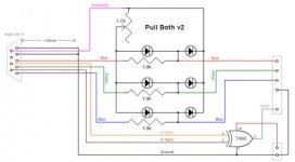
pull2-rgba-xor.jpg

According to Wikipedia EGA doubles the number of colour lines so there is 6 in total (2 each). I was wondering, could a modification of the above circuit be made where the Intensity connection is replaced by a similar connection from each secondary R/G/B (or is it primary? I'm not quite sure which of the two would be the 'higher value' EDIT: missed that Wikipedia listed the secondaries as 'Intensity') to its respective primary one.

Do you think this method would work? I was thinking of designing a small board that could do either CGA and EGA based on what you hook up (CGA Intensity vs EGA secondaries) and just bridging the R/G/B higher connections together so the Intensity triggers all 3 at once.
 
Last edited:
You could do the conversion using a resistor divider with 2 resistors on the high side (like a simplified resistor ladder DAC with only 2 bits input). However the GBS-8200 will not sync to 21.8KHz EGA. I know it's marketed as supporting EGA, but what they really mean is "medium resolution arcade video" at 25KHz. 21.8KHz is just outside the range supported by their conversion chip. I've experimented with modifying the registers of the conversion chip directly, but there's no way to get it to work at 21.8KHz--the chip is more or less fixed at just a few horizontal frequencies. Quite disappointing.

I suppose you could get the EGA card to output the 200 line modes only (at 15.7KHz) which should work. You will still need the XOR gate to create the combined sync signal. The vertical sync input doesn't seem to do anything on the GBS-8200 in non-VGA modes.
 
Thats disappointing. I was hoping when it said it did EGA, it was flexible enough in its allowable frequencies to actually do 'computer' EGA.

I did find a custom firmware thread for the GBS-8200 over at Shmups, but it seems more to add additional video out modes, and a couple of times when people asked about supporting input frequencies outside 15/25/31KHz their posts generally went unanswered.

...Anyway, as the PC1640 does have DIP settings for plain CGA I can still use it for testing both machines. I was hoping to try out the full EGA mode though (the monitor it came with is only the monochrome model). I may still design a small PCB to sit inside one of those cheap plastic DB15HD/DB9 hoods, as a simple converter cable would still be of some use. Still deciding if I should attempt the full Commodore DAC version as well, as it would fix the brown/dark yellow issue (even if it would be more bulky).

My hope is to get a VGA card in the 1640 in the long run anyway so its not really a dealbreaker if I don't get to see things in glorious 640x350x16.


EDIT: ...Are there any similar video converter boards in the same price range as the GBS-8200? This is the only one I've seen (that did VGA out) that isn't over $100.
 
Last edited:
My experiments were based on info from that thread. I'm not aware of other boards in that price range. I wound up getting a really good deal on an NEC Multisync (the original) which, after a lot of cleanup, works fine for my purposes.
 
On a side note, I have a Amstrad PC-CM CGA monitor from a 1512SD that I have been troubleshooting as of late. Would it be possible to test it with a standard IBM CGA card and a simple re-cabling job?
 
I too have a PC-CM monitor (and a PC-MD for the 1640), sadly the cables have been sliced off both and will need work to reattach (hence me looking into alternatives to test the machines before doing so).
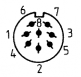
I haven't done any actual work on mine yet, but AFAIK the PC1512 is standard CGA using an 8 pin DIN connection. I got the following information from the Amstrad PC1512 Technical Reference Manual (and a link to the PC1640 version is available here):
pc1512.video.png
(plug from monitor)
1 Composite H & V sync
2 Intensity
3 GND
4 Black
5 Green
6 Blue
7 GND
8 Red

I'm not sure if other machines like an IBM use CSync or have separate syncs. You'll have to make an sync adapter/combiner circuit if they do.
 
The circuit Tronix linked earlier just used an XOR gate (74LS86) and a resistor. A quick Google also turned up this one just using a diode and a resistor.
syncadd.png

However, the page it came from says "The only requirement is that both the horizontal and vertical sync signals must be negative".
 
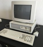
Thanks will get to this soon. It would be nice to find that at least one part of this system that works, given it's good cosmetic condition. I know that the FDD is dead, but would like to test the monitor and keyboard as well.

IMG_0732.jpg
 

Attachments

  • IMG_0732.jpg
    IMG_0732.jpg
    87 KB · Views: 1
Mine isn't in as good of a condition, but is the PC1512HD20 with a (probably dead) 20MB HDD (though peeking inside the case of my PC1640SD it looks to also have a HDD/controller card as well).

...If you do need to replace the floppy drive there are modern devices called 'floppy emulators' that connect in place of the floppy drive and use a flashdrive/SD card containing disk images. I know you can get 720K '3.5in' models, but unsure if they make them specifically for 360K/'5.25'.
HxC does sell a device that does older floppy drive emulation, and he also apparently made a custom firmware (still in beta) for the cheaper 'Gotek' floppy emulators which does a lot of the functionality of his device. You do need to buy a (cheap) USB serial programmer to flash his firmware to the device though.
 
This one has a HDD controller card but the original owner pulled the HDD. I currently have an HxC floppy emulator in a DTK-Data 1000 now, which I tried on the 1512, along with another working 360K FDD, and same result - infinite blinking cursor after please wait.....

I was able to test this by dropping in a Hercules + mono display.

The also makes me think the FDD controller is non-functioning as well.

Testing the monitor on another system will hopefully reveal more. I predict several components on the motherboard may be in need of replacing, however.
 
Mine isn't in as good of a condition, but is the PC1512HD20 with a (probably dead) 20MB HDD (though peeking inside the case of my PC1640SD it looks to also have a HDD/controller card as well).

If that's a factory-fitted HDD (rather than a third-party addition) do you know the exact model? The MESS folks are looking for that information at the moment.
 
If that's a factory-fitted HDD (rather than a third-party addition) do you know the exact model? The MESS folks are looking for that information at the moment.

Well I finally got both cases open today (one thing I do not miss about old computers is the level of shielding these things used...) and so far the only horror story seems to be the massive amount of green corrosion/buildup on the CMOS/AA battery terminals.

Anyway, looking at the PC1512HD20 I would say that it is possible the HDD that was in it is the original (everything else in the machine seemed stock, correct HDD bezel, front bay shieldings seemed both untouched/correct screws [unlike the PC1640], etc).

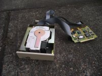
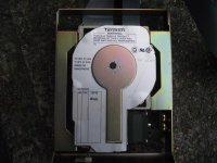
The HDD is a Tandon TM262R. The HDD controller board is something Western Digital. 5 seconds on Google turned up this, which seems to match up with what I found (WDC bought Tandon in order to 'create' the first WD HDDs).
pc1512hd20.1.jpg pc1512hd20.2.jpg pc1512hd20.3.jpg

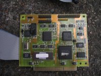
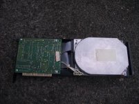
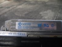
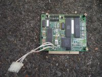
And for completeness, the PC1640SD also had a third party HDD. Since the second drive bay was taken up by an aftermarket 3.5" HDD+bracket the HDD+controller were screwed to a full length ISA bracket. That HDD was a Kyocera KC-30B, along with another WD card.
pc1640sd.1.jpg pc1640sd.2.jpg pc1640sd.3.jpg

Feel free to pass the info about the HDD along to the MESS team.
 
I have a monitorless 1512 too and need to rig up something to supply power and get video output.

Power shouldn't be an issue but the video output is still causing some concern - particular the 'black' pin on the connector. I haven't got the link to hand but someone on a russian forum suggested there's some circuitry in the 1512's monitor that's further processing the image before it's display, and this would need to be implemented in any sort of video adapter made for this machine. It's more than the yellow->brown conversion from what I could see.

Be great if someone could figure this out - My electronics/video knowledge is still very lacking!
 
Back
Top