pcdata76
Experienced Member
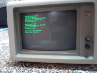
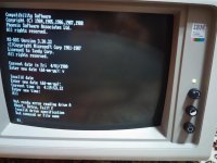
During the week-end, I've decided to remove the cabinet of my newly bought 5153 (together with a late-model 5160) to check inside and clean the internals thoroughly because it was filling the room with heavy smoke odor within minutes after operation. Here, IBM gear is usually used mainly in public and private companies due to the high selling price compared with the clones and the one that i've bought was not an exception (It had inventory tags of a company on the side of the case) Smoking was allowed in public and closed buildings during these years, so it is expected that they smell like an ashtray.
Other issues are:
-Brightness and contrast potentiometers were flaky
-focus was a bit off (It's my feeling and may not be an issue with the monitor. I didn't use a monitor having such a coarse dot pitch ever and the only other CGA monitor that i have is a Sony Trinitron having very fine (0.24mm) pitch and giving very clear picture with clearly visible scanlines.)
-white was a bit blue tinted.
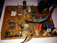
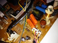
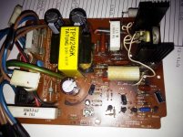
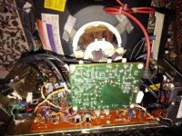
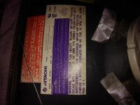
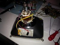
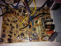
So I've removed the case, discharged the tube (nothing was left after a day since last operation) and removed all connectors, boards and tube from the casing. My initial intention was just the washing the casing, boards and the tube and spraying the potentiometers with contact cleaner, but after seeing some heat damaged capacitors (see photos below, plastic sleeve of some of the capacitors has been shrunk down and they are located usually very close to a power resistor) and rust at the bottommost metallic parts probably due to water intake, I've decided to do a complete overhaul. Some part of the power supply PCB was also seriously blackened (actually burned) due to local excessive heat and there was cold solder joints in this region too.
Mainboard:
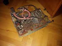
Power Supply Board:
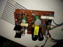
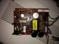
CRT Board:
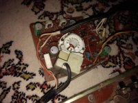
I've removed electrolytic caps from power supply board and measured them. Some of them were close to the spec but the rest were at least two to three times high in ESR. I also verified resistors and film capacitors in the heat affected region in the power supply board and they were all in spec.
Since obtaining good quality capacitors locally (i mean within the country by local) is almost impossible, I've made the list of the capacitors and will order them from a reputable online electronic component store. Before placing the order, i've decided to add my 5151 and 8513 recovered from electronics recycling center last year to the list, I've dismantled them and created the list of capacitors. I wanted to share the list here for a future reference, since they could be different than service manual sometimes. For example, my 8513 is an early model (S/N starting with 23-XXX) and service manual found on the net covers only the late revisions (S/N having 72-XX prefix) and they have totally different circuit layout and components in compared with mine except the model name.
Anyway, here is the list:
IBM 5151 (220V Version, probably only mains transformer is different in 110V versions)
5151
Note that C505 is a special kind of capacitor, bipolar and low ESR electrolytic. It is not easy to get them, so i'm planning to use some paralleled film caps in place of that capacitor.
IBM 5153 (100/240V version)
5153
IBM 8513-002, S/N starting with 23 (200-240V Version)
8513
Before ending the topic, i just want to tell few more words about my cleaning procedure.
-Disassemble everything (casing, boards, tube, all other things like degauss coil and switches etc.) Make photos during disassembly, it really helps during reassembly especially if device contains too much and various kinds of fasteners. Note the location of the connectors too.
-Wash the casing using warm soapy water. Rub the outer parts of the casing (except tags and labels) using Cif (a cream detergent having lightly abrasive material inside which is often used here in the cleaning of sinks and bathtubs) with a brush.
-Clean the tube thoroughly using wet towels but be careful to not rub much the bell area (it has graphite (aquadag) coating which is required for proper operation and could be easily removed by heavy rubbing) If the tube is very dirty, i usually wash it too under warm water by rubbing with a soft brush. Leave tube to dry (especially complete drying of the deflection coils need some time) Be also careful to not damage to the delicate neck of the tube. Hold CRT always using two hands from the sides firmly, be careful to not drop! Never ever lift the tube from the neck. Also, always put a soft and thick cloth under the face of the tube during cleaning/drying periods to prevent scratches.
If boards are dirty beyond vacuum cleaning as in the current case with smoke residue (Take necessary ESD precautions during the job):
-Desolder parts like coils and transformers (including flyback transformer) in which water could be trapped in for long time and causing issues
-Clean desoldered parts using wet towel.
-Wash the circuit board with warm soapy water and using a soft brush (I prefer 1" paintbrush for this job)
-Rinse circuit board using demineralized water and/or IPA.
-Leave circuit board for at least a day (in summer, i keep more in winter) in a warm place to dry.
-Resolder desoldered parts, perform other component replacements/repairs if needed.
-Reassemble everything.
I'll picture the whole assembly procedure and post in the forum after completion of the recapping job.
Other issues are:
-Brightness and contrast potentiometers were flaky
-focus was a bit off (It's my feeling and may not be an issue with the monitor. I didn't use a monitor having such a coarse dot pitch ever and the only other CGA monitor that i have is a Sony Trinitron having very fine (0.24mm) pitch and giving very clear picture with clearly visible scanlines.)
-white was a bit blue tinted.
So I've removed the case, discharged the tube (nothing was left after a day since last operation) and removed all connectors, boards and tube from the casing. My initial intention was just the washing the casing, boards and the tube and spraying the potentiometers with contact cleaner, but after seeing some heat damaged capacitors (see photos below, plastic sleeve of some of the capacitors has been shrunk down and they are located usually very close to a power resistor) and rust at the bottommost metallic parts probably due to water intake, I've decided to do a complete overhaul. Some part of the power supply PCB was also seriously blackened (actually burned) due to local excessive heat and there was cold solder joints in this region too.
Mainboard:

Power Supply Board:


CRT Board:

I've removed electrolytic caps from power supply board and measured them. Some of them were close to the spec but the rest were at least two to three times high in ESR. I also verified resistors and film capacitors in the heat affected region in the power supply board and they were all in spec.
Since obtaining good quality capacitors locally (i mean within the country by local) is almost impossible, I've made the list of the capacitors and will order them from a reputable online electronic component store. Before placing the order, i've decided to add my 5151 and 8513 recovered from electronics recycling center last year to the list, I've dismantled them and created the list of capacitors. I wanted to share the list here for a future reference, since they could be different than service manual sometimes. For example, my 8513 is an early model (S/N starting with 23-XXX) and service manual found on the net covers only the late revisions (S/N having 72-XX prefix) and they have totally different circuit layout and components in compared with mine except the model name.
Anyway, here is the list:
IBM 5151 (220V Version, probably only mains transformer is different in 110V versions)
5151
Note that C505 is a special kind of capacitor, bipolar and low ESR electrolytic. It is not easy to get them, so i'm planning to use some paralleled film caps in place of that capacitor.
IBM 5153 (100/240V version)
5153
IBM 8513-002, S/N starting with 23 (200-240V Version)
8513
Before ending the topic, i just want to tell few more words about my cleaning procedure.
-Disassemble everything (casing, boards, tube, all other things like degauss coil and switches etc.) Make photos during disassembly, it really helps during reassembly especially if device contains too much and various kinds of fasteners. Note the location of the connectors too.
-Wash the casing using warm soapy water. Rub the outer parts of the casing (except tags and labels) using Cif (a cream detergent having lightly abrasive material inside which is often used here in the cleaning of sinks and bathtubs) with a brush.
-Clean the tube thoroughly using wet towels but be careful to not rub much the bell area (it has graphite (aquadag) coating which is required for proper operation and could be easily removed by heavy rubbing) If the tube is very dirty, i usually wash it too under warm water by rubbing with a soft brush. Leave tube to dry (especially complete drying of the deflection coils need some time) Be also careful to not damage to the delicate neck of the tube. Hold CRT always using two hands from the sides firmly, be careful to not drop! Never ever lift the tube from the neck. Also, always put a soft and thick cloth under the face of the tube during cleaning/drying periods to prevent scratches.
If boards are dirty beyond vacuum cleaning as in the current case with smoke residue (Take necessary ESD precautions during the job):
-Desolder parts like coils and transformers (including flyback transformer) in which water could be trapped in for long time and causing issues
-Clean desoldered parts using wet towel.
-Wash the circuit board with warm soapy water and using a soft brush (I prefer 1" paintbrush for this job)
-Rinse circuit board using demineralized water and/or IPA.
-Leave circuit board for at least a day (in summer, i keep more in winter) in a warm place to dry.
-Resolder desoldered parts, perform other component replacements/repairs if needed.
-Reassemble everything.
I'll picture the whole assembly procedure and post in the forum after completion of the recapping job.
Attachments
Last edited:


