• Please review our updated Terms and Rules here

Faulty IBM 5151

th3bar0n

Experienced Member
Joined
Oct 14, 2017
Messages
51
Location
London
I was recently given a faulty IBM 5151 monitor.

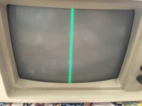
It powers on fine and has good brightness levels but the horizontal view has collapsed to a narrow strip in the centre of the screen.

The picture below is trying to display a directory listing but each file name is shrunk to a blob.

Has anyone seen this type of failure before or knows what it might be?

5151.jpg
 
Likely the deflection circuit has failed. Unless you've worked on the inside of a TV or monitor (and thus know the dangers), then the repairs should be left to someone who has done such a repair.
 
Last edited:
Yeah, especially in the horizontal circuit, please leave that for an old TV guy unless you've done it before.
 
There's going to come a time and place when "old TV guys" or people with long experience working on CRT's aren't either around anymore or hard to find. So I don't think there is anything wrong with giving more advice other than give it to someone else.

Up until I fixed my 5151 a few months ago (which coincidentally appears to have had the same issue) I had never touched the inside of a CRT as I was well aware of the potential dangers which was a major put off. But I went ahead with it anyway as I did my homework to fully prepare myself for the potential dangers and how to properly discharge the tube and work safely within the CRT. I even went to the extra step of leaving the monitor unplugged and untouched for at least a month while I sourced parts (I had to get the replacement flyback from the US which took a few weeks in itself) so to ensure there would be little charge if any at all. When it came to discharging the tube it seemed to be a prudent move as there appeared to be no more life in it, but I did it multiple times just in case.

In the end I replaced the flyback transformer + HOT, did a full recap (found a couple of caps on the horizontal circuit which weren't giving good readings after removing) and did a general clean up to remove years of built up dust. Yes I did the shotgun approach without actually properly diagnosing exactly what caused the fault and hence learning for next time, but it worked and I now have a fully functional beautifully looking 5151. I have since repaired a 1084S doing basically the same thing, but in it's case I was 100% sure it was the flyback as it had all the telltale signs. It's also fully working and I'm still alive to tell the tale.

The main thing, which needs to be stressed in my opinion, is if you are going to attempt anything like this that you need to be fully aware of the potential dangers and procedures/steps you need to take to mitigate these dangers and work safely. If you do your homework, prepare yourself properly, there's no reason why you can't do it yourself.
 
Thank you everyone for the help. I have some electronics experience but not with CRTs and all the hazards that come with them.

I guess I was trying to gauge the scale of the problem. I'm keen (but scared!) to attempt a repair.
I think I'd feel comfortable recapping the horizontal circuit but a bit more wary to go beyond that.

Flamin Joe, you've given me some confidence to attempt a recap at least.
I've done some reading around and there seems to be a low ESR cap that seems susceptible to going bad.

Can you remember the caps you replaced and did you have trouble sourcing equivalent replacements?
 
If you've touched the inside of a CRT, it's not going to work anymore, unless someone ever gets a CRT rebuilding shop working again. :)
 
Looking at the service manual online, this problem is relatively simple. Since you have the tube showing a line means the HOT is running because it produces high voltage to light the tube. The problem has to be in the current path for the horizontal yoke: capacitor C505, the yoke itself, coils L502, L503, L504. Look at those coils for solder joints and measure them with an ohmmeter, they should measure almost zero ohms. Check the yoke connector for solder cracks and the yoke, it should measure maybe 10 ohms. Examine capacitor C510 for solder cracks. If that capacitor fails, it will probably have a crack in the body of it.

Larry G aka "old TV guy"
 
Last edited:
LCD's are worse. Almost impossible to regrow the crystals outside the right environment. :p

This is one of my biggest beefs with the "advancement" of modern technology. We keep getting further and further from things that individuals or small groups of individuals can build. For example, if I were desperate (or just had the time and money) I'm sure I could build a working triode, or a point contact transistor. But a FET or LM741?

Something that really bugs me about the CRT rebuilding project at ETF is that I have no doubt that if I didn't have to work for a living, I could have set up shop and been rebuilding tubes years ago, had I their resources. But don't get me wrong, I don't blame them. I'm not there and don't know what goes on there, but I do know how hard it is to get a group of people to work together to accomplish something like that on a very limited budget.
 
... I had never touched the inside of a CRT as I was well aware of the potential dangers which was a major put off. But I went ahead with it anyway as I did my homework to fully prepare myself for the potential dangers and how to properly discharge the tube and work safely within the CRT. ...

If you've touched the inside of a CRT, it's not going to work anymore, unless someone ever gets a CRT rebuilding shop working again. :)

I believe Flamin Joe should have said CRT Type Monitor instead of simply saying CRT. But I think most of us understood what he was saying!! Lighten up KC9UDX ;)
 
Finally got back to this.

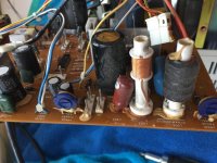
C505 seems to be ok, no obvious bulging or leaking.
20180529_120527825_iOS.jpg

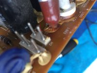
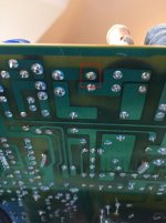
L502 (170312) has definite leakage visible at the base, as well as on the underside of the PCB.
20180529_120535762_iOS.jpg
20180529_120656254_iOS.jpg

Given my inexperience, I'm thinking to just replace both C505 and L502 while it's all apart. Everything else looks good so I'm inclined to leave them be at this point.

What are appropriate replacements? I've read C505 is hard to replace like-for-like and I have no clue about L502.

Any advice greatly appreciated as always, thanks!
 
L502 (170312) has definite leakage visible at the base, as well as on the underside of the PCB.

Any advice greatly appreciated as always, thanks!

L502 isn't a capacitor, it's a coil (which doesn't leak). What you see is epoxy to hold it (as well as L503 and L505) to the board and prevent oscillation (which it apparently has failed to do since you appear to have a loose solder connection underneath). The discoloration is likely due to the mixture of the lamination on the coil mixing with the epoxy when it was applied (likely hot at that time).

As for the capacitors not "showing" any signs of leakage---it's almost impossible to accurately gauge an electrolytic cap in-circuit just from looks alone (although a leaking capacitor definitely should be replaced). They generally have to be removed and measured---and even a capacitance measurement doesn't tell much about the Q factor of it:

http://www.capacitorguide.com/q-factor/

And as in most electronics, electrolytic capacitors are the first thing to usually dry out and malfunction:

https://www.antiqueradio.org/recap.htm
 
Last edited:
Buy a multimeter so you can check resistance (ohms). They cost next to nothing. If L502 is bad, I doubt there will be a replacement except from another display as a parts donor.
Yoke capacitors such as C505 seldom fail unless it looks cracked or the leads on it corroded. The entire yoke path of all the components I listed (except the capacitor)
can be checked with one simple measurement. I have a 5151 myself that I can open up and show you but you need the meter.

Holy crap, I just saw the solder joint you highlighted in red. That's got to be it. Remove the solder, work the coil lead with a nail file then resolder. It will be crusted up with carbon from burning.
Yes the yoke current can cause it to burn. The epoxy glue on top has darkened from the burn. I would leave that alone. It won't matter on a coil. The coil leads will be fragile from the heat that has generated
so could damage it if you try to remove the coil or the glue.

Larry G


Great, many thanks. Will get to work on that coil and report back.
 
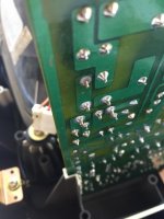
Ok - old solder removed and lead filed to a shine..

20180624_160913313_iOS.jpg

Amateurish dollop of fresh solder..

20180624_162637825_iOS.jpg


Reassemble, switch on.. and.....

20180629_085357793_iOS.jpg


:clap:


I guess it was quite a simple fix in the end :blush: but would never have had the confidence to try without everyone's help and suggestions.. so thank you!!
 
That solder joint is doomed. It may last a while, just long enough that you'll forget where to look for it. I'm not trying to rail on you but you shouldn't need to file lead, and solder should never be applied as a dollop.
 
I suspect that you may have not used enough heat at the joint or possibly lead-free solder. Find some good ole Kester 44 rosin - core and go back over it with a good amount of heat on the iron.
 
Back
Top