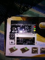
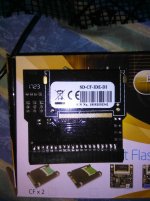
Hello all! After watching many videos on the XT-IDE, I decided to dust of my soldering iron and purchase a kit. However, I need some advice on what CF adapter and card to purchase for an IBM PC. I previously purchased a rather cheap-looking adapter and card and could not get them working in an AT with an IDE card. My question is which card should I get? I defiantly want a card with a bracket so I can retrieve the card from behind the system; I do not care what size the card is. I have found a few on eBay (https://www.ebay.com/itm/1PC-40-Pin...Bootable-Computer-Accessories-ws/153229277921 or https://www.ebay.com/itm/Monoprice-...m=232879532129&_trksid=p2047675.c100005.m1851) but I wanted to get a second opinion this time. Thanks!
Upcoming Events:
- VCF South West - June 14 - 16, Davidson-Gundy Alumni Center at University of Texas at Dallas
- VCF West - Aug 2 - 3, Computer History Museum, Mountain View, CA
- VCF Midwest - Sept 7 - 8 2024, Schaumburg, IL
- VCF SoCal - Mid February 2025, Location TBD, Southern CA
- VCF East - April 2025, Infoage Museum, Wall NJ
-
Please review our updated Terms and Rules here
- Forums
- Companies
- IBM Computers, PCs, Clones and Descendants
- PCs and Clones (XT and early AT class machines)
You are using an out of date browser. It may not display this or other websites correctly.
You should upgrade or use an alternative browser.
You should upgrade or use an alternative browser.
Best CF Adapter and Card for XT-IDE?
- Thread starter RHopple
- Start date
2icebitn
Banned
Casey
Veteran Member
I just bought 2 from Monoprice.View attachment 50138View attachment 50139
These are meant to plug directly into a mobo idea header or a card's header presumably. My immediate intention is to use this with a 386, but may buy a newer xt ide kit. Have the original bare circuit card which I never used. Maybe I'll try that first.
That is the one I previously purchased, the one that did not work with the AT. Perhaps it is the controller? I will take these suggestions into consideration, and thank you for your ideas.
modem7
10k Member
If you have not read it already, I recommend that you read the 'Problems' page at [here].Hello all! After watching many videos on the XT-IDE, I decided to dust of my soldering iron and purchase a kit.
The first-listed item there is very common, and is not restricted to the XT-IDE.
Chuck(G)
25k Member
glitch
Veteran Member
Pretty sure I shipped your kit out yesterday 
I buy the little black CF adapters that plug right onto the IDE header, when I use CF adapters on XT-IDEs. They will take power from the XT-IDE as long as you have JP3 closed. I buy the cheapest ones I can find, and get 5-10 at a time, to make sure I get one that works. I've had a lot of quality issues with them, from every single vendor I've purchased from, so I figure I might as well not spend more than I have to! I am also working on a CF mezzanine board for the XT-IDE, but haven't gotten around to actually *finishing* it yet.
Personally, I tend to use industrial Flash modules (DOMs) with XT-IDEs. I transfer everything over Ethernet or serial though, so I don't need the removable aspect of CF cards. Be sure to zap your CF card with `dd`, WIPEDISK, or some similar utility to remove all of the old partitioning/formatting information.
Pretty sure I shipped your kit out yesterday
I buy the little black CF adapters that plug right onto the IDE header, when I use CF adapters on XT-IDEs. They will take power from the XT-IDE as long as you have JP3 closed. I buy the cheapest ones I can find, and get 5-10 at a time, to make sure I get one that works. I've had a lot of quality issues with them, from every single vendor I've purchased from, so I figure I might as well not spend more than I have to! I am also working on a CF mezzanine board for the XT-IDE, but haven't gotten around to actually *finishing* it yet.
Personally, I tend to use industrial Flash modules (DOMs) with XT-IDEs. I transfer everything over Ethernet or serial though, so I don't need the removable aspect of CF cards. Be sure to zap your CF card with `dd`, WIPEDISK, or some similar utility to remove all of the old partitioning/formatting information.
That you did!
I have it all soldered up and in my 5150, but the computer gives the 601 error everytime it posts. After the error, the BIOS displays its address and then does not find the CF card installed. When it says the master and slave are not installed, the system boots to BASIC. I tripple checked my solder work, and although its not that great, there are no short circuits or other problems. I'm sure it has something to do with the 601 error because the system boots to the floppy without the XT-IDE installed. Any ideas?
modem7
10k Member
On face value, it sounds like the XT-IDE's I/O ports are conflicting with those of the floppy controller.I have it all soldered up and in my 5150, but the computer gives the 601 error everytime it posts. After the error, the BIOS displays its address and then does not find the CF card installed. When it says the master and slave are not installed, the system boots to BASIC. I tripple checked my solder work, and although its not that great, there are no short circuits or other problems. I'm sure it has something to do with the 601 error because the system boots to the floppy without the XT-IDE installed. Any ideas?
Assuming good kit construction (for now), I think the first thing to investigate is the setting of the SW1 switches (per [here]).
* Has switch block SW1 been soldered on in the correct orientation; the switch 1 end towards the card center ?
* If so, for the default setting of 300h for the I/O starting address, switches 1 and 2 (A9 and A8) need to be on, with the remaining SW1 switches off. For on versus off, that depends on the type of switch block that was supplied; see [here]. Is that correct ?
* If so, try rocking the switches back and forth in case one is not quite 'home'.
I found that some CF card adapters have an "interesting" voltage regulation method for achieve 3v3 and 5v operation of the CF card. Basically they run the 5v line through a pair of diodes and rely on voltage drop across them. Which is pants. But even worse, some always have one in line, meaning 5v is way out of spec. These interfaces are often the cause of write errors in my experience, since they don't conform to either standard.
Hence - run the CF card at 5v, and confirm with a multimeter how power is getting to the CF itself, and jumper past the problem diode if it's there. Other than that, these are purely passive devices and can't really do too much wrong.
Hence - run the CF card at 5v, and confirm with a multimeter how power is getting to the CF itself, and jumper past the problem diode if it's there. Other than that, these are purely passive devices and can't really do too much wrong.
glitch
Veteran Member
Yeah, many of them do run power through a pair of diodes for 3.3V. The better of the cheap ones have a jumper to bypass the diodes.
I have been poking around with my multimeter on continuity mode and believe I have discovered the issue. Whenever the first two switches on Switch 1 are activated (either one), switch three is also activated, changing the address from 300h to 380h. I cannot see the issue as the soldering is good there, but I will desolder anyways to make sure.
Chuck(G)
25k Member
IIRC (and it's been awhile), on the V1 card, I had the same problem. The pad area for the switch legs that wasn't covered by resist and large ground pad on one side created some problems. I cleaned and enlarged the pad area a bit and the problems went away.


