shawnerz
Experienced Member
Hello all.
My name is Shawn. I will apologize in advance. This post may get long and involved.
I am the owner of a TEMPESTed Grid Gridcase (8086) that originally had a broken EL display. The display was visibly cracked and could not repaired. The display is a rare Sanyo LJ640U07. I thought I could get lucky and hack in a newer Sanyo LJ640U34. That ended disastrously in a $450 failure.
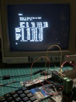
My next goal was to verify that the video circuit was still alive. The goal was to connect an external monitor to the Grid and get a display. The laptop boots form the floppy. I can type 'dir' and see drive activity. So, I know the computer is alive.
I want to connect an external monitor and see a command prompt. I have been unsuccessful.
I attached a picture of the motherboard. The 15 pin female connector is the video connector. Of course, it's not a standard pin configuration.
I have an Digilent USB Analog Discovery 2 module that I use as an 'scope. The pins of interest are pins 1 - 5. There are display supply voltages on 6-8, and mostly grounds on 9-15.
One interesting fact is pin 5 is not connected to anything inside the mating connector. Of course, the display is a monochrome display. So, wouldn't only 1 be needed? If two are being used, is it red and blue? Blue and green? Green and red?
Looking at online documentation, an analog display basically needs H-Sync, V-Sync, Red, Green, and Blue.
Using pins and alligator clips, I've manually connected the Grid video lines to a variety of newer LCD displays and older CRT displays. Other than make them "come alive" for a few seconds, I cannot get anything to appear on the display.
I will attach screen shots of the waveforms on the different pins. The waveforms look OK to me, but I can't get a monitor to recognize them.
Perhaps someone will say, "Oh, the waveforms look great. Just plug in a <insert magical device> and it will work just fine!" HA!
I am thinking of "throwing in" some sort of 6 inch tablet display. Worse case, run an cable outside of the laptop and connect it to a standard monitor.
If the people of the forum could give me some pointers, or tell me what I'm doing wrong, or what I need to to, I would appreciate it. Any (reasonable) suggestion would be appreciated.
Thank you,
-Shawn


