• Please review our updated Terms and Rules here

Xerox 6060 restoration

I passed on that -- I have 4 6300s and 2 6060s and out of all of them only one always works. I have another that decides randomly when it wants to work after power is applied -- it either shows POST just fine, or just sits there. I have two spare 6300 motherboards that are spare parts at this point because they don't work either. I have 3 color 6300 monitors which all work but each has some issue; I have 3 mono 6300 monitors and only one works; I have two 6060 monitors and neither works.

I'm alarmed at how many of these are dying in storage, and how, despite no obvious corrosion or flaws, they just stop working even after significant capacitor replacement.

I do wish you luck though. Please keep us posted. Give me hope I can someday repair mine.
 
With Xerox 6060, welcome to the M24 owner club!!!

I can give you hope.

I have one full working M24
I have one full working M24SP
I have one full working M21
I have one full working M240
I have one M24 with power supply dead, but when putting another in, it works, except of floppy operation
I have anther M24 (with "sidecar" - extension box) where power suppy is Ok, but floppy operation problem
- The floppy operation problem at both is read error, currently* investigating in it.
I have another dead M240, power supply issue
I have one coior monitor which basically works fine, except of after not using it for long time, it needs up to 30 minutes to warm up and switch high voltage on. No idea what it is
I have one monochrome monitor with 25 pin connector which fully works
I have one monochrome monitor with composite in for M240 which fully works
I have NEC Multisync I (the original one) which works in digital mode with 25 to 9 pin adapter, and currently* I am trying to mix color signals with intensity signal to get it also working in analogue mode, for TFT usage.

* means currently, means not really currently, but currently interrupted - waether is too good and too hot to play computer...

Power supply of M24/M240 is bad topic. Hard to repair, hard to test outside of chassis, because of it's mechanical structure. Maybe I should replace the internals with modern power supply...
 
I passed on that -- I have 4 6300s and 2 6060s and out of all of them only one always works. I have another that decides randomly when it wants to work after power is applied -- it either shows POST just fine, or just sits there. I have two spare 6300 motherboards that are spare parts at this point because they don't work either. I have 3 color 6300 monitors which all work but each has some issue; I have 3 mono 6300 monitors and only one works; I have two 6060 monitors and neither works.

I'm alarmed at how many of these are dying in storage, and how, despite no obvious corrosion or flaws, they just stop working even after significant capacitor replacement.

I do wish you luck though. Please keep us posted. Give me hope I can someday repair mine.

I’m sorry and surprised to hear that. The M24 I have back in Italy works flawlessly (the few times a year I get to use it), and the 6300 I have in the States also never had any problem - I just added a 3.5” drive a few weeks ago. Monitors for both (both monochrome) are fine. I even have an M240 in Italy which I acquired in absolutely shocking conditions, which stil boots up (having replaced the power supply) and only has a (hopefully minor) memory problem which I am still tracking down.

I’m afraid analog (and high-voltage) electronics is not my strong suit so I don’t think I can help much with troubleshooting the monitors - which is a shame, as I’ve never seen a colour monitor for these - either in real life (I believe they were far too expensive for retail customers in Italy back in the day) or even for sale. Maybe other people here can.

Basic question on the 6300 with erratic power-on behaviour - did you check the power rails with a meter? When it doesn’t POST, do you get anything at all on the parallel port?

And also - thanks! Yes I will keep you posted, I had wanted a 6060 for a long time to “almost” complete my collection (I’ve given up on finding a Logabax... unless I move to France one day...)
 
With Xerox 6060, welcome to the M24 owner club!!!

Thank you! Although I’ve been in the club since the late ‘80s :D - but in fairness I only became active again in the last couple of years.

Nice collection - I have never seen a sidecar for the M24!

I have NEC Multisync I (the original one) which works in digital mode with 25 to 9 pin adapter, and currently* I am trying to mix color signals with intensity signal to get it also working in analogue mode, for TFT usage.

I had started on that project too a while back, even got some components for it - had to put it on standby for lack of time

Power supply of M24/M240 is bad topic. Hard to repair, hard to test outside of chassis, because of it's mechanical structure. Maybe I should replace the internals with modern power supply...

I never had to, but presumably one could adapt a modern-ish AT power supply and just add a +15V rail with a custom-voltage boost switching regulator from eBay?
 
Basic question on the 6300 with erratic power-on behaviour - did you check the power rails with a meter? When it doesn’t POST, do you get anything at all on the parallel port?

I haven't measured the PSU yet. On the LPT port, when it doesn't POST I see nothing; when it does POST, I see numbers up to 45h (normal) and then it's in the POST display normally.

I had wanted a 6060 for a long time to “almost” complete my collection (I’ve given up on finding a Logabax... unless I move to France one day...)

I'll likely never see an M24 (I'm in the USA) unless I trade someone for it.

Nice collection - I have never seen a sidecar for the M24!

Yes, I've never seen one either! Only in a photo.

I never had to, but presumably one could adapt a modern-ish AT power supply and just add a +15V rail with a custom-voltage boost switching regulator from eBay?

Someday I'll understand all of the words in that sentence.
 
Valerio, do we know from elsewhere? Because I know italian guy which also travels a lot to USA and has large collection of M24 and 6060, 6300, etc...
 
Someday I'll understand all of the words in that sentence.

Apologies - that was indeed a bit cryptic. Let me elaborate a bit.

If I had to replace an M24/AT&T power supply with a modern one, I would do the following:

ATX power supply

It seems there is a large number of form factors for modern PC PSUs (eg see here) but I would stick with the classic ATX. Specifically I would go for a Startech 300W ATX 20-pin power supply. I have never used this one before but I have bought plenty of Startech products in the past and they were of good durable quality. I have a number of Startech AT power supplies (sadly, no longer on sale) for my 486 etc. and they are whisper-quiet. No affiliation - just a satisfied customer!

Adapters

The M24 has four main internal DC voltage rail connectors on its power supply.
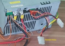
M24_PSU.jpg

1. A connector for +5V/GND/GND/+12V for internal drives. Internal drives use the classic 4-pin Molex connectors - no need for adapters here, the ATX power supply can be connected to the drives directly.
2. A +15V/GND connector for monochrome monitors (connector "B" in the photo). We'll get back to this later.
3. A +12V/-12V connector for the ISA bus (connector "A" in the photo)
4. Two large +5V/GND screw posts for the main motherboard/bus converter supply

I think the cleanest way to connect to the ATX PSU is to buy a cheap adapter that has has a 20-pin female ATX connector - something like this. You will also need a screw terminal block of sufficient size to accept the two large red/black wires.

Cut off the unwanted end and refer to a pinout guide like this to connect the following:

- All +5V wires (pins 4, 6, 19, and 20) together into one end of a screw terminal block. Do not connect the wire from pin 9 - that's the +5V standby (always-on) supply, leave that unconnected.
- At least four GND wires (choose from pins 3, 5, 7, 13, 15, 16, 17) into another one of the screw terminal block openings
- The wire from pin 14 (/PS_ON) to any GND wire. This tells the ATX PSU to switch itself on. Alternatively you can put a switch between /PS_ON and GND and control the PSU that way.

This takes care of the main motherboard/bus converter power supply. Now we need to connect the +12V/-12V line. I don't have access to an original power supply right now so I can't tell exactly what type of connector this is, but I know it's a male connector on the PSU side so at worst we can connect the two wires from the AT PSU (pins 10 and 12 for +12V/-12V) to individual pins (those from breadboard jumper wires should do) and insert those into the female connector, securing the joint with good old fashioned electrician tape :D. Alternatively we can run a new wire to the motherboard, where the connector is male - I think individual female dupont connectors would fit, but again I can't be sure until I get a chance to check.

15VDC line

This is where it gets a bit tricky. We need to generate a +15V rail. This is used exclusively to power the monochrome monitor - if you are using an adapter to VGA, this is not needed. I also think this may not be needed by the colour monitor as that has its own power supply, but never having seen one I can't be sure. Anyway, I think the best way to do this is to use a DC-to-DC converter, called a boost or step-up converter, to obtain +15V from +12V. eBay has a large offering of these, but many are "variable-voltage" output that needs to be trimmed. In my experience I have always found these a bit fiddly - I usually prefer fixed-output-voltage regulators like this one. Mind the amperage - I would not go below a 2A rating as the M24 Theory of Operations manual specifies a current draw up to 1.8A on this line. I would source the +12V from one of the Molex connectors for the disk drives. The connector is the same physical size as the +12V/-12V one, so the same consideration apply for connecting it up.

Dimensions

All the above should work for a temporary replacement and/or for testing. For a permanent replacement it's worth noting that ATX PSUs are deeper that the M24 one (150mm vs 112mm) so I am not sure if they would fit. At a stretch I guess it would be possible to remove the ATX PSU outer enclosure (!!DANGER!!) and relocate the fan outside of the PSU into the location of the original fan, and house the ATX PSU PCB into a smaller enclosure (possibly re-using the original enclosure if the original PSU is truly beyond repair).

It is also worth mentioning that the workings of the original power supply are documented in beautiful detail in the Theory of Operations manual, so if at all possible troubleshooting and/or repair of original units is worth a try (even though I have never done so myself beyond general cleaning and fuse replacement).

Disclaimer

I have not done any of the things above - this is just theory. Electricity kills. If you don't know what you are doing, don't.
 
Last edited:
Valerio, do we know from elsewhere? Because I know italian guy which also travels a lot to USA and has large collection of M24 and 6060, 6300, etc...

I don't know but sadly I doubt it - I've hardly ever been to Germany! Also my collection is anything but "large" - just one of each of M24, M240, 6300, and (yet to arrive) 6060. But I'd be happy to be introduced to your other Italian friend!
 
Yes, that's Vincenzo. So the M24 owner club is getting bigger and bigger, and here in this forum is the center of the universe. :)

Valerio, good thoughts about replacing the internals of the power supply. The original power supply repair task is very difficult, ok we have diagram and description, but the mechanical separation of low and high voltage part is a bad thing. If you want to analyze that psu, you have to get it out of it's chassis, need a long connection cable for the two parts of the PSU, fix both boards that they can't touch each other, be care full that you don't touch at the wrong spots, it needs some airflow, and you need some electrical load on the output connectors. That PSU is completeley dying if you power on without enough load. And you are dying if you touch at the wrong place.
 
Last edited:
Dear fellow Olivetti collectors,

yes, I'm here. I'm on this forum from years. Strange because some of you who write I'm not "here" actually replied to my posts here more than one time.

I'm not dead, yet!

Strange. Also my large collection of M24, M240, etc. etc … everything works! For the power supplies, no problems on my side: I know how to repair them.
Other topic are the motherboards: in this case spotting the issue, the failing TTL or LSI, is more complicate as you need to use a logic analyzer to track down the issue and then to desolder without damaging too much the motherboard.

Repair a motherboard it's a long story and takes time and dedication. Anyway I've replacement parts for nearly everything.

I can assure all of you that out of a few (less than 3 or 4) of all the Olivetti computers in my large collection (M10, M15, M22, M24, M28, M250, M250E, M280, M290, M300, M380 all models, P500, P700, P750, P800 etc.etc … everything works flawlessly.

Last addition to my collection is a wonderful M24 dated January 1985 with Bios 1.1. That is probably the second most aesthetically beautiful M24 I've ever got in my collection! THe first one is an M24 SP that seems like new.

The motherboard is like new, even no dust on it. And more unique than rare, the Varta battery is PERFECT! No spills. Seems to be purchased yesterday. I desoldered it, anyway, but I will keep it in the collection.

Plastics are perfectly white. It also has the rare Toshiba floppy drives model 5401 with the vertical trap door. The keyboard is an ANK2462 with 102 keys with US Ascii layout and two intense cyan and orange special keys. The mechanic of the keys is the later version with red plastic, so it has a better mechanism and better touch. The keyboard is like new, also. No yellowing, all the locks are intact.

Additionally I'm getting another (I already have 4 or 5) Olivetti M19, but this has a wonderful (and very rare) original color monitor (a CGA with DB9 connector), plus a working hard disk.

Then I got an M111 (working but with dead backlighting), an M211 with an Error 6 from the Keyboard test (that I'm still tracking down to try to fix it) and a Philos Color 45 in working condition.

My collection is growing … need to find another place to store it.

Greetings to everybody, unless I'm dying before you can actually reply to this post.

Vincenzo.
 
Last edited:
Hahaha! Wonderfull!

I need to visit you one day. You have M22... Wow! Never seen a M19 with color monitor. (I got a M300-02 and M4 modulo 46 recently, nice little machines)

Can you take pictures of your machines and put them on an album here in the forum?

Are you also able to fix PSU for M380C/XP1, M240?

democenter.jpg
My wet dream would be to fill this room with your and my machines and retransform it into permanent exibition... This used to be THE demo center... (do you know this building?)
 
Last edited:
Hi Stefan,

You are more than welcome to visit me. Some other Olivetti Collector came to see a part of my collection as it is spread in 3 places and not all in "ready to be visible" form.
If you are in hurry to see it, you can start by watching the video of my fully functional Programma 101 on Youtube, searching for "programma 101 Vincenzo". I will try to post other videos but I have to fight with my unwillingness to post videos or images on the internet.

But at least you can see pictures of one of my two Olivetti M22 on the site Vintage-laptops. The owner of the site, a Russian guy, wanted to purchase my Olivetti M22, he was so insisting. I resisted! :) But at least I took pics of the best Olivetti M22 of the two, with a working EL backlight! The other is severely damaged by a battery spill. I have all the replacement parts to repair it, but I have too many things in the pipe to do. I got it without power supplies and with one of the two motherboards and the memory board heavily damaged by acid. Hopefully I have a spare power supply, motherboards, memory board, LCD and floppy drive.

I believe the two rarest items I own related to the M22 are the Olivetti M22 original manual (in english) plus original floppies (also in english) and the modem expressely designed for the weird expansion slot of the M22, with its software and manual. One of the floppies, the typical "Getting to know M22" was heavily corrupted when I received it, but I was able to reconstruct the damaged GWBasic program files. Heavy reverse engineering.
You can actually see the software running in the front view on the Vintage-Laptops dot com website.

I will send you by mail the pics of the M19 with color monitor once I have tracked down the keyboard not responding keys.

Ciao, Vincenzo.


My wet dream would be to work for the Museum of History computer in Mountain View (which I visited 4 or 5 times). Try to repair the Programma 101 they have in poor conditions and without too much "respect" to its importance in the computing world history in the first showcase shelf on the right. If I am unable to due to complex mechanic problem (belt dissolved or gears broken), bring it personalltly to the guys in Ivrea (Gastone, Sergio and Sandro) for repair. Finally bring it back and present it in a decent way as "the first personal computer of the history". A
Maybe recreating the "tree of computers" like in the IBM advertisement, with the P101 on top and IBM PC at the bottom. Finallt add some more Olivettis to the exibitions. Like the Olivetti M22 (unfortunately not known), one of the rarest computers of the history or other computers who won the Compasso d'Oro, italian award for industrial design.

I don't know what is this building but it reminds me an Olivetti headquarter, maybe the one in Germany (in Frankfurt?).

Just to present all the versions of M24 I have, I need and entire hall of the museum.

I still owe you some images of Olivetti floppy but I am lazy on that side. If you come bring floppies and you can copy what you want.

Bye.
 
Why museum in US? We reopen Olivetti Frankfurt Demo Center in that building. If the space of original demo center is not enough, we take the complete ground floor including the rooms which have been the service center. We can also take the 1st floor if this is not enough, once housing the electronics workshops and training center. Still not enough, well... the whole building? Both towers... I have a friend nearby, didn't met him for about 20 years, but a few month ago, we met in supermarket and we are back to close contact now. Also he used to be apprentice with me there, started just a year after me, but he had the opportunity to stay several years after the trainig as a technician in "Appllication departement" where they custmized machines for clients. I think he also would love that idea...
 
It works!

It works!

Apologies for the long delay... other things got in the way of this restoration.

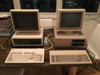
Anyway, I received the Xerox 6060 I had ordered, and by some incredible luck a few weeks later I saw for sale a matching Xerox monitor - and not just any monitor, a black and white one! I really like monochrome white monitors, and I’ve never seen any monochrome monitor in a color other than green, so this was a great find. Now I just need to find an amber one to complete my collection :)

67E20232-3B0F-480E-A784-5035440D63A0.jpg

The 6060 is in great condition, just in need of a minor clean. The problem with it (it was sold as not working) was indeed the power supply. I am not an expert in switching power supplies and Olivetti’s have a strange topology, using variable reactors (!!) and multiple transformers. After a few basic checks I determined that fixing it was not going to be quick or easy (for me) so I set about replacing it with a modern one, along the lines of my previous post in this thread.

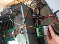
I used a Startech 300W ATX power supply, connected to an ATX breakout board with screw terminals so that it was easy to experiment with it. Most connections are straightforward, ie GND, +5V, +12V (without this, the keyboard won’t work), and -12V (without this, the serial port won’t work). The tricky one was the +15V for the monitor, as expected. I used the DC-DC boost converter from eBay that I linked in the previous post, which was supposedly rated at 2A. However, although it did work, it got very hot very quickly. The monitor draws around 1.3A-1.4A. I then switched to another DC-DC converter, based on the XL6009 chip (yes I know I said I didn’t like variable voltage converters, but this one seems to work fine). It gets moderately warm but nothing too hot to touch, even after hours of use.

67B4A991-370D-4046-B00D-39C29F2FBB6E.jpg

Of course this is a temporary arrangement, and a few more modifications are needed to make it suitably permanent...
 
One problem, as I mentioned previously, is that the ATX power supply is deeper than the original power supply, so a direct swap just won’t fit.

View attachment 57376

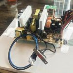
However, by a very fortunate coincidence the internal PCB of the ATX will exactly fit depth-wise into the housing of the original one! Here is where it gets a bit messy. First I disconnected the (extremely quiet) 12V fan from the ATX supply PCB. The I cut off the wires going to the mains switch/socket, and I replaced them with two new wires ending with 6.3mm female spade connectors. I also disconnected the 110V/230V switch from the ATX housing, keeping the wires intact. Also, I cut off the cables that led to unnecessary power connectors (like the Pentium 4 4-pin molex, or SATA drive power), making sure to properly insulate the cut-off ends. Finally, I added brass standoffs at the corner of the PCB (using existing holes).

View attachment 57378

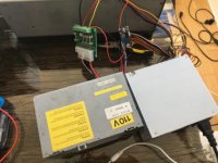
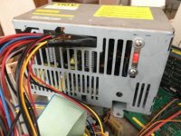
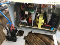
This was now ready to be fitted into the original housing. I drilled three small holes on the bottom of the housing so I could fasten the standoffs with some tiny screws (the is a hole in one of the corners so the fourth standoff cannot be screwed in). The power cables can be routed out of the housing from the gap at the back near where the 5V and GND heavy-gauge wires were screwed in. It’s quite fiddly and I wrapped the cable in “gorilla” duct tape to protect them from the sharp edges of the housing. I also fastened the mains voltage selector between the grills with a couple of washers.

View attachment 57379

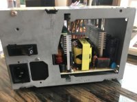
Now it was time to re-attach the front panel of the housing. Unfortunately I had to remove the slave IEC mains connector since it just would not fit with the new PCB in place. I later replaced it with a black plastic cover. I connected the new spade connectors to the original switch and closed the panel - done!

View attachment 57380

View attachment 57381

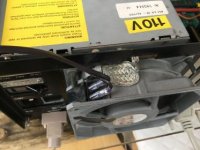
Well, not quite done yet... the original power supply also provided power to the fan. I intend to replace the fan with a (quieter!!) 12V one, but in the mean time I need to power the existing (mains) one. This is easy - I crimped two 2.8mm female spade connectors to a mains cable, and this allows me to power the fan while I wait for the 12V one to arrive.

4E00A5FC-30A0-4137-A2FC-C1D008DF4050.jpg

The last step will be to integrate all the connectors and the voltage booster onto a custom PCB, which will make it much cleaner.
 
It looks like most of the pictures in my last post did not upload correctly. Here they are again.

Size comparison:

C3EEE38C-766D-41AD-8A7F-80348B470353.jpg

Adapted ATX PCB:

0C306424-EE7E-42C2-B451-28BABCF9D2C5.jpg

Back of the original housing:

DAA4C351-990B-4A44-B237-F838D786AB9D.jpg

Back of the original housing:

765FC3D8-E83A-41A5-BFF1-71EAA24EEEB0.jpg

73AC106C-76F1-417F-A2AF-4487DA40A2A6.jpg

I hope the upload works this time!
 
Back
Top