• Please review our updated Terms and Rules here

IBM PCjr but really IBM JX ROM burning question

Joined
Dec 30, 2012
Messages
27
Location
Koo-Wee-Rup, Victoria, Australia
Hi all -

I have been able to read the IBM JX ROMs using my EPROM burner and successfully burn them to 27512s.

But life cannot be this simple, and of course, the IBM JX does not like the copied ROMs one bit. Reading online, there are different pinouts and I should read the technical reference guide to see what may be different. But there isn't a technical reference guide (that I have seen!) for the IBM JX.

I was hoping that a PCjr specialist may have a EPROM/ROM adaptor design that I can build to use EPROMs for the JX.

Looking at some photos online, the PCjr does not appear to have socketed ROMs like the JX does - which is interesting and may be a problem for this discussion.

I also have been unsuccessful in finding any IBM PCjr BIOS/ROM upgrades on webpages.

Any assistance would be appreciated.

Thanks;

Anthony
http://www.thepcmuseum.com/ibmjx
 
What's the original part number for the JX ROMs? All the pinouts should be JEDEC standard. A 27C512 is a 64 KByte part. The Jr has A14/15 tied to A14 on the mainboard so it always selects the correct 32K page in the ROM. If the JX ROMs are not 64 KByte each, you will need to 'tile' them in the ROM - eg. duplicated it enough times to fill the ROM part completely. The JX may leave A15 floating - in which case a 32K image in only the first half of the ROM will fail.

There were no PCjr upgrades really - at least not by IBM. You could replace the system ROM with a cartridge, but I'm not aware of any that ever did that. The JR-IDE option ROM adds a lot of extras. I'm currently working on a new version of that now as well.

-A
 
FWIW IBM bragged that the JX (in AU or NZ mag, can't remember which) had a 1Mbit ROM, something they beleived to be a first for a personal computer.
And when I look up the part number (231000) - I find lots of models of 1Mbit Mask ROMs.

Doesn't make sense to me to have 128KB in the AU/NZ version - I think half is probably blank - but the machines were modified for AU/NZ not made for us specifically - so perhaps they just had those parts in stock and didnt want to change parts?

Here's a random 23C1000 datasheet which might help you with pinout.
https://www.datasheetarchive.com/pd...2c7efd15ef9634b7baa&type=O&term=23C1000%20ROM

Edit: it seems if you put a 27512 in place of a 231000, you'll end up with address pin 16 going to the OE pin of the 27512 - everything else looks like it lines up, so you may just need to pull out pin 22 and tie to ground?
 
Last edited:
Are you absolutely positive that's a 64K ROM and not 128k? (IE, have you peeked-around the upper memory of a working JX to see if there actually is 128K of ROM and for whatever reason your EPROM burner is dumping the wrong part number?) I ask because the documentation for a JX Emulator says this:

ROM Images (JX Mode, Japanese)
This program loads following ROM image files from current working directory.

BASE_E.ROM : E0000h-EFFFFh
BASE_F.ROM : F0000h-FFFFFh
FONT_8.ROM : Font ROM 80000h-8FFFFh
FONT_9.ROM : Font ROM 90000h-9FFFFh
FONT_A.ROM : Font ROM A0000h-AFFFFh
FONT_B.ROM : Font ROM B0000h-BFFFFh

It seems like they kind of expect something to be there in the E-page.

The Tandy 1000HX also used a 28 pin 1Mbit mask ROM. (About half is the system BIOS, the rest is a ROM disk image of a minimal DOS 2.1.) The pinout of its ROM matches up with the 28 pin variant of the 23C1000 in the linked datasheet. I don't know what the JX might have in there. (There are references that say the Japanese version has a bunch of ROM space taken up by Kanji characters. Maybe that's not used in an english version, but there's no reason to think that they changed the decoding hardware to accommodate that.) Assuming it is actually a 128K ROM then I suppose the first task would be to go spelunking around a working JX, if you have one, and see if there's anything in the E page to see if it really is kosher to sub a 64k ROM. If it is then I would think adopting the pinout of a 27512 would probably work. I'm not sure if the better strategy would be to tie pin 22 to ground or to piggyback it to pin 20. Either should do?

If you *do* need the full 128k unfortunately it doesn't look like there's any EPROM equivalent of a 1Mbit EPROM in a 28 pin package; there are literally no pins left to use for programming. Looking at the pinout of a 32 pin 28010 EEPROM it looks like you could *pretty much* stick it in the socket (with some pins bent up to not go into the matching holes) with the top four pins hanging out and jumper as so (chip -> socket):

32 -> 28 (bend up pin 30 on chip)
2 -> 22 ( bend up pin 24 on chip)
24 -> chip #22/ socket #20 (Pin 22 stays seated in hole 20 of the socket, tack chip #24 to it)

Probably want a pull-up resistor between VCC and pin 31 on the chip.
 
Last edited:
@Spidersweb

Yes, you are right. My poster does indicate 1 MBit ROM. So maybe it is 128k. I’ll have another play tomorrow.

I assumed (silly) that the Kanji ROM which is missing in our JXs was the other 64k.

@Eudimorphodon

Awesome find! Have never seen that emulator or that documentation before! You have given me something to read and learn about. Thanks!

Anthony
 
There are many parts to this thread...

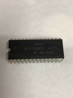
Firstly, the part numbers you identified (8530K9, 8532K9, etc...)
are actually manufacturing date codes : 8530 = 30th week of 1985, 8532 = 32nd week of 1985 )
I know this is very confusing, but most chips have 4-digit date codes (especially starting with 7,8,9 [70's, 80's, 90's ]

The chip type is actually 231000 , MPD probably indicates Motorola or Fujitsu manufacturing.
"23" indicates a "mask" rom (ie. mass-produced using a "mask" of the binary data , and not "programmed" )
[ "27" is used to indicate a UV erasable eprom. So 23xxxx and 27xxxx chips are often interchangeable ]

"1000" indicate a 1Mbit rom ( = 128 Kbyte )

HOWEVER... (and this is where it gets messy... )
An equivalent 1Mbit EPROM (271000), MUST have 32 pins , whereas the 231000 has 28 pins.

The reason for this is that a programmable eprom (27-series) needs a pin dedicated for programming.
(usually a high voltage pin 12.5V, 21V or 25V for "burning" the data")

A 1 Mbit MASK rom needs 8 pins for data, 17 pins for addressing ( 2 ^ 17 = 131072 address locations = 128 Kbyte ), 1 VCC pin, 1 GDN pin & 1 Chip Enable (CE) pin
for a total of 28 pins.

A 1 Mbit EPROM, needs at minimum 29 pins, because 1 pin is used for programming ,
so a 32-pin eprom is needed.

This problem only happens with 1Mbit eproms because it is the only situation
when the "mask" rom and the "EPROM" have different number of pins.

To make matters worse, when 1 Mbit eproms became common,
they used the existing JEDEC pinout, which was just a little different than mask roms.
(...this is because the 32-pin eprom had 3 "extra" pins, so they used one as an address pin ).

However demand grew to create 32-pin eproms which could replace 28-pin MASK roms.
To do this, the 32-pin 1Mbit EPROMs, had to break from the JEDEC standard
and duplicate the same pinout as the 28-pin mask rom
(...confused yet ? ).
So a special "mask-compatible" eprom was created to do this.
This is 32-pin eprom, which can replace a 28-pin mask eprom.

Some board designers were actually smart enough to use 32-pin sockets
even-though the mask rom only had 28-pins, but for those who didn't,
the 32-pin eprom will have 4-pin sticking out of the socket.
These are non-critical pins (...sort of) so they won't affect the operation of the chip.

[ I can add more techno-babble to this thread, but I'll keep that for another time ]

The bottom line is that you will need a 32-pin mask-compatible eprom, not a 27C512.
Examples of this are Hitachi 27c301, ST 27c1000, NEC 27c1000
(... The JEDEC versions are Hitachi 27c101, ST 27c1001, NEC 27c1001 ; you DON'T want those ! )

[ And just to REALLY mess things up, the datasheet you provided is from MX ,
.... and for whatever insane reason, they reversed their part code so MX 27c1000 is JEDEC = 27c1001 from everyone else.
Their mask version is the 27c1001 .... which is the EXACT opposite of every other manufacturer.
This has caused me no end of grief ! ]

So I've rambled on way too long, and probably gave everyone a headache.
... but I can help you solve your issue.

The only problem I see that the rom image you are using is wrong; it should be 128kbyes in size, not 64kbytes.
I can only assume that whoever made the rom dump assumed it was a 27c512 because it had 28 pins.

You need to find the correct 128Kbyte image to make this work.
I can supply and program the eprom if need be.

LMK,
Stephan
 
Last edited:
Photos of my busted front panel JX:

https://www.retrotronics.org/2020/05/ibm-5511-pcjx-japanese-version/

I recall seeing Kanji when I last powered it on. Can a Japanese version be converted to an Australian/NZ version with a ROM swap-out? (main and character?)

I've never tried it, but I'd say that's quite likely. Ours were the same motherboard, just with things removed.
Only things I wouldn't be sure of would be if you need to also remove the second 1mbit ROM (I imagine you dont), and if the english ROM is compatible with the EXVIDEO card (although you can just unplug that).

One question while we're here, what are the other chips on that EXVIDEO card? In adverts I've seen IBM Japan advertise "VRAM" seperately and wondered if any of the chips on the EXVIDEO cards were RAM or just logic.
 
Looking at some photos online, the PCjr does not appear to have socketed ROMs like the JX does - which is interesting and may be a problem for this discussion.

FWIW my PCjr has socketed ROMs. Looks factory, I don't see any signs of re-work on the board in that area.
 
Wow. I just got these emailed to me from Aram - I am wondering if this is where these came from? Thanks very much - I have not seen the logic drawings.

Anthony

They came from Aram. But re-OCRd them in Acrobat and moved the quality/size slider more than a little bit. 160 MB to 12 and still look ok.
 
Photos of my busted front panel JX:

https://www.retrotronics.org/2020/05/ibm-5511-pcjx-japanese-version/

I recall seeing Kanji when I last powered it on. Can a Japanese version be converted to an Australian/NZ version with a ROM swap-out? (main and character?)

The Australian JX does not have sockets where the Kanji ROM is - I am guessing you can - this is what I am trying to test with Aram and why I am trying to burn him a ROM. I have about 10 Australian JX units with all manner of accessories, but I have zero Japanese JX units. I'm going to have another trial of reading the ROM with my EEPROM burner, hoping to see what I can get.

Aram could not get any of the disks working on my website, which seems to indicate there is a compatibility issue with PCjr/AUJX and JPJX OR his drives are dead. For the record, standard 1.44MB floppy drives DO work in a JX and read in 720k format should your drive be dead.

Anthony
 
Alright. I have used Mikes PCJRCART program to download the ROM from my most up to date JX.

I am either incompetent or do not know how to read the ROM using my EEPROM reader as it does not associate a 28 PIN DIP with a 128k (1MB) ROM.

SO - Should I want to get this ROM to Aram or whoever, how would I assemble the contents in a package on a ROM, considering there is 100k of data here. Mikes program shows the addressing in memory, but how would this be laid out for a single ROM?

Alternatively, is there an adaptor I can get or some other software that can make my TL866-II Plus read it to save me the headache?

I'm sorry to ask these questions, but I have a bit of a knowledge gap here.

Thanks;

Anthony
 

Attachments

  • JX Roms - PCJRCART.zip
    76.3 KB · Views: 6
I am either incompetent or do not know how to read the ROM using my EEPROM reader as it does not associate a 28 PIN DIP with a 128k (1MB) ROM.

The 128Kb 32-pin eprom equivalent to a 28-pin mask rom is HITACHI 27c301 (or ST 27c1000)

Your programmer "should" support this eprom type.

Unfortunately, there is catch...

On the 28-pin mask rom you are trying to read , VCC (5V) is on pin 28 .
On a 32-pin eprom (like the 27c301), the VCC is pin 32.

So if you try to read the 28-pin mask rom as a 27c301 eprom, you are not getting the VCC to the correct pin.

What you would need to do is make a small jumper/wire connection on your programmer's ZIF socket.

A 28 pin chip has 14 pins on each side, and a 32 pin eprom has 16 pins (...well duh !),
so on the right side of the ZIF socket, just put a small wire from pin/slot 16 to pin 14
(... which is equivalent to pin 32 to pin 28 on the chip).

So here is what you do :
1- Select Hitachi 27c301 eprom type on your programmer
2- Put your 28-pin mask eprom on the programmer
3- Put a small jumper wire from pin/slot 16 (on the right side of the ZIF socket) to pin 14 (which should be the top corner pin of your mask rom).
(this should provide VCC to pin 28 of you mask rom )
4- Read the eprom

You "should" get a 128kbyte image from this.

If you can view the contents, I would assume you should find some readable text stringa.
This would show that you got valid data.

Let me know if you have any questions.

Cheers,
Steph
 
Back
Top