• Please review our updated Terms and Rules here

Inboard 386/PC 2mb expansion CLONE

stynx

Experienced Member
Joined
May 20, 2013
Messages
184
Location
Germany
As there is a lot of demand for new 2 and 4 mb expansion boards for the Inboard 386/PC, I had originally begun to develop a clone of that card. I had lost interest a few months into development and left the further work on my PCB layouts alone.

Harrison Frasier has contacted me a few weeks ago asking about info on my work. Since I was not able to invest more time into that project, I gave him all the PCB layouts and info I could find.

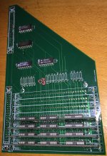
Based on the data Harrison designed a new PCB prototype.
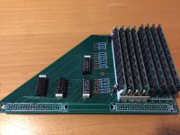
He built and successfully tested the 2mb prototype a few days ago. There are still some uncertain thing to figure out but it's a big step forward.
LVdlM8X.jpg


Further work and development:
Harrison is now the owner and project manager of the expansion. I will get 2 bare prototype PCB from him to test different memory modules, TTL ICs and maybe add some modifications to get 4 or 8mb to work. My part is now to support and beta-test (which im happy with). Im glad that Harrison has taken the project up and got it to another milestone.

I think we are very close :)

This thread is meant as a central info point for the project.
references:
Seeking-memory-card-for-InBoard-386/page3
 
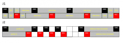
I have built one prototype with one of the PCB i was given by Harrison. It seems to work normally and has caused no problems so far. I have tinkered a bit with the not connected signal on pin 15 of the J2 connector. It is neither another RAS-enable line nor a CAS-enable line. We help from someone who owns a 4mb expansion for the inboard to measure the connections of pins 11-27 on the J2 connector.
The white areas need to be verified on the 4Mb expansion.

50597625068_4501221964_o.png

The address-lines are inverted by two 74AS1004 (=7404) and routed to the corresponding address line on the RAM ICs. The address line 9 in the picture should be checked since it is not connected on the 2Mb card.
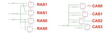
The RAS and CAS signals should be generated by the two 74AS1032 ICs. The address lines from the 74'04 inverters and generated RAS/CAS signals from the 74'32 or-gates are routed to the RAM ICs through 22 Ohm resistors via resistor networks (4308R-102 220) on the 2Mb card (should be the same on the 4Mb card).

50598542307_6c34a4a6c0_o.png

My knowledge regarding 386 memory controllers is very limited (non-existent). I would really like to see a comment on this thread :)

50597706633_9f7037262e_o.jpg

Success with 4mb :)

50597802458_5096574527_o.jpg

-Jonas
 
Last edited:
We have to test a bit more but i think that Harrison will be able to offer a 4Mb expansion in the near future :-D

-Jonas
 
Another working prototype (low effort) without resistors and capacitors. 4 Simms directly soldered to the card.
PS2 modules would be nice but they will not work since the have bidirectional parity lines. The Inboards needs separate parity input and output lines. It may be possible to take a 74'244 and use the ^WE lines (seem to have identical signals) to separate the parity access between read and write. May be and interesting project :p
50599838468_6bac247158_o.jpg
-Jonas
 
I have desoldered the RAS-generator PAL (301094-001) from one of my defective Inboards and could read out its contents.
the equations look like this:
Code:
PAL20L8B
1: A22
2: A21
3: A20
4: A19
5: A18
6: A17
7: A16
8: A23
9: from PAL U75
10: from PAL U76
11:from PAL U74
12 GND
13:
14:
15: RAS to 4Mb Bank
16:
17:
18:
19:
20:
21: RAS0 to 1Mb Bank (1)
22: RAS1 to 1Mb Bank (2)
23:
24 VCC


Inputs:


1, 2, 3, 4, 5, 6, 7, 8, 9, 10, 11, 13, 14, 16, 17, 18, 19, 20, 21, 23


Outputs:


15 (Combinatorial, No output feedback, Active low)
17 (Combinatorial, Output feedback output, Active low)
18 (Combinatorial, Output feedback output, Active low)
19 (Combinatorial, Output feedback output, Active low)
20 (Combinatorial, Output feedback output, Active low)
21 (Combinatorial, Output feedback output, Active low)
22 (Combinatorial, No output feedback, Active low)


Equations:


/o15 = (A22)& /(A21)& /(A19)& /(A18)& /(A23) & i9 & i16 +
       /(A22)& (A20)& (A18)& /(A23) & i9 & i16 & /i23 +
       /(A22)& (A20)& (A19)& /(A23) & i9 & i16 & /i23 +
       /(A22)& (A21)& /(A23) & i9 & i16 +
       (A22)& /(A21)& /(A20)& /(A23) & i9 & i16 +
       i11 & /i16
o15.oe = vcc


/o17 = (A22)& /(A18)+
       (A21)& /(A18)+
       /(A18)& i23 +
       /(A18)& (A17)+
       (A19)& /(A18)+
       /(A20)& /(A18)
o17.oe = vcc


/o18 = (A22)& /(A19)+
       /(A19)& i23 +
       /(A19)& (A18)+
       (A21)& /(A19)+
       /(A20)& /i4
o18.oe = vcc


/o19 = (A18)& (A17)& (A16)& /i10 & i13 & i14 +
       /(A18)& /(A17)& /(A23) & i13 +
       (A20)& /(A23) & i13 & /i23 +
       /(A19)& /(A23) & i13 +
       (A22)& /(A23) & i13 +
       (A23) & i13 & i14 +
       (A21)& /(A23) & i13
o19.oe = vcc


/o20 = (A22)& (A21)& (A20)& (A19)& (A18)& (A17)& (A16)& (A23) & i9 & /i10 & i14 +
       /(A22)& /(A21)& /(A19)& /(A18)& /(A23) & i9 +
       /(A22)& /(A21)& /(A23) & i9 & i23 +
       /(A22)& /(A21)& /(A20)& /(A23) & i9 +
       (A22)& /(A21)& (A20)& (A19)& /(A23) & i9 & /i14 +
       /i16
o20.oe = vcc


/o21 = i11 & /i16 +
       /(A22)& (A21)& /(A20)& /(A19)& /(A18)& /(A23) & i9 & i16 +
       /(A22)& /(A21)& (A20)& (A18)& /(A23) & i9 & i16 & /i23 +
       /(A22)& /(A21)& (A20)& (A19)& /(A23) & i9 & i16 & /i23
o21.oe = vcc


/o22 = i11 & /i16 +
       /(A22)& (A21)& (A20)& /(A19)& /(A18)& /(A23) & i9 & i16 +
       /(A22)& (A21)& /(A20)& (A18)& /(A23) & i9 & i16 +
       /(A22)& (A21)& /(A20)& (A19)& /(A23) & i9 & i16
o22.oe = vcc

this means:

for the 4mb address space:
0x14 0000 - 0x3F FFFF
0x18 0000 - 0x38 FFFF
0x20 0000 - 0x3F FFFF
0x40 0000 - 0x4F FFFF
0x40 0000 - 0x53 FFFF

Resulting in 0x140000 - 0x53FFFF (4Mb with a 256k shift up)

The two 1Mb banks of the 2Mb expansion are similar:
0x140000 - 0x23FFFF for bank 1 and
0x240000 - 0x3FFFF for bank 2

To address more memory, we would have to swap out the RAS-generator PAL (301094-001) with a new modified one. Since the inboards seem to go easily defective, i would not recommend this.
I have the jedec file of the 301094-001 PAL if anyone is interested :)

-Jonas
 
To address more memory, we would have to swap out the RAS-generator PAL (301094-001) with a new modified one. Since the inboards seem to go easily defective, i would not recommend this.
I don't follow the reasoning. Replacing an aging part on a failure prone board should only improve its reliability if done with proper technique
 
Are those PALs compatible with new Atmel ones? Like ATF16, ATF22 and ATF1508... PALs are like one of the things that fails after capacitors, which is what kills a lot of Commodore PETs etc... they do die due to age eventually.

Anyway very exciting development! I think I had messaged you before asking about things in a similar line as Harrison I guess he was justa bit more motivated lol. I'll be wanting to make 2 4 or 8MB variants if that becomes possible... it may also be possible to bodge a wire directly from the CPU address lines if it isn't available on the memory bus already. The more memory on the 32bit piggyback card the better especially for things like running win 3.x on 8bit bus machines!

Edit: Also I have a batch of 5161 expansion senders... I haven't assembled them but I have most of the parts, perhaps I will have time over the holidays to play with that. Computer reset probably still has a bunch of expansion boxes with receivers.

You are right by saying that the PALs are aging. I had salvaged 3 RAS-generator PALS (TIPAL20L8, PL20L8 and PAL20L8 ) from different boards but only the last one had (seemingly) all the correct equations. the TIPAL was completely dead and the PL20L8 was part empty and gave a different checksum from time to time. While testing the new memory expansion, my only non-Parity inboard went bad. It now freezes at checking the 256k XMS on the card. I have the experience that even with proper antistatic measures the inboard can turn dead all of the sudden. I may unsolder and read out all other PALs on the dead boards. maybe i can fix at least one of them?

Up to 16Mb may possible with only changing the 301094 PAL on the inboard. The most straight forward solution would be replacing the 2 RAS-signals for the 2Mb expansion with 2 additional address lines.

-Jonas
 
Are those PALs compatible with new Atmel ones? Like ATF16, ATF22 and ATF1508... PALs are like one of the things that fails after capacitors, which is what kills a lot of Commodore PETs etc... they do die due to age eventually.

The common GALs (16/20/22V8/10s) were specifically designed to be fairly universal replacements for a good selection of earlier PAL devices, at least electrically. (I don't think you can just flash the same .jed files onto them, you'll need to recompile the equations for the newer device.)
 
I have read out some more PALs. They are hosted

here.

Since I own three defective Inbooards and one I of them is very damaged (corroded traces), I will continue to unsolder the PAL-ICs from it and try to get the jedec files from them. We may be able to save some of the currently defective Inboards if every chip can be replaced.

-Jonas
 
Last edited:
Win 3.x

Win 3.x

Are those PALs compatible with new Atmel ones? Like ATF16, ATF22 and ATF1508... PALs are like one of the things that fails after capacitors, which is what kills a lot of Commodore PETs etc... they do die due to age eventually.

Anyway very exciting development! I think I had messaged you before asking about things in a similar line as Harrison I guess he was justa bit more motivated lol. I'll be wanting to make 2 4 or 8MB variants if that becomes possible... it may also be possible to bodge a wire directly from the CPU address lines if it isn't available on the memory bus already. The more memory on the 32bit piggyback card the better especially for things like running win 3.x on 8bit bus machines!

Edit: Also I have a batch of 5161 expansion senders... I haven't assembled them but I have most of the parts, perhaps I will have time over the holidays to play with that. Computer reset probably still has a bunch of expansion boxes with receivers.

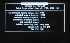
Windows 3.11 already runs well with my 4MB Intel memory expansion card for the InBoard (which yields 5MB total with it's base 1MB). More memory alone won't be enough though - you also need to upgrade to 486 CPU (I used a 25/50 Cyrix but the standard oscillator caps it at 33MHz unless you replace it), and you also need to replace a subset of the Win 3.1 OS files with ones from the special edition of Win 3.0 for the InBoard to get the Keyboard to function properly and a few other things when running Win in enhanced mode (well documented elsewhere on this board). An additional 4MB would be nice though, but I've not run short of memory running any of dozens of major Win 3.x apps.

Regards,
Mike
 
I agree that 4Mb (4.3Mb) memory is good for most applications and games from 1994. But I want to get the maximum that would be possible. 8Mb instead of 4mb on the expansion would even allow Quake and Duke3D to run (even though the cpu speed will be lacking).

An Inboard equipped with a 46Mhz oscillator, 8mhz XT-bus and Transcomputer 486 adapter with an AMD5x86 (94Mhz) and 4mb memory expansion is fast enough to rum Doom (1.9) in fullscreen at 12-13fps. With these modifications the XT is elevated to the speed of a 486DX33 class computer. The Cyrix 586 at 4x mode is maybe a bit faster than that... but I don't have one yet.

-Jonas
 
I'll add I also have an orchid ramquest, any idea how that would interact with the piggyback boards? I haven't tried it... it has a Xilinx hardwired FPGA on it, probalby not possible to reverse engineer that.
 
I'd love to see one of these made for the Inboard 386/AT (memory board pictured here). The AT version has a different connector than the XT version (although apparently early versions of the XT card used the same or at least a similar style of connector), but at least the pin count is the same. Although, there are a few notable differences...first, the RAM count is configured manually through DIP switches, instead of automatically. It also can only accept up to 2MB of piggyback memory, rather than 4MB (at least according to the manual's instructions on setting the switches). And after looking at the pictures, the memory board seems to use 4x 74LS1008 quad 2 input AND buffer/drivers... Anyway though, could someone possibly teach me how I might probe the pins to determine the pinout for the connector, or at least tell me the thought process that is used to determine what is what?
 
Your fist step will be to identify all GND and VCC pins on the connector. You can easily do that by using a LED, a 3V batterie and two wires or use a multimeter. Then you should test the pins of the expansion against the data-pins of the memory (should be 36 with 32 data lines and 4 parity lines). This will help you reducing the number of lines that have to be tested. The data-lines are directly connected to the expansion connector on the Inboard 386. The raining lines are most likely routed through resistors and (partly) through the logic ICs. The address lines may be inverted by the logic chips. The RAS and CAS signals can be identified by the lines connected to the respective lines of the memory chips. The RAS and CAS signals are generated on the Inboard expansion by combining them out of several signals on the expansion connector. If any signal lines are still not identified/not connected, you may have additional signals available (maybe intended for a 4Mb expansion). Its a bit of work but it is pretty easy to do.

I don't own a Inboard AT and cannot help you with these steps.

-Jonas
 
I know it has been a while and wanted to follow up. Due to other reasons I had to shelve this project right after the holidays, and hope to resume it one day!

I had a 2MB board working rock solid with 8x256K 80ns SIMMs but was never able to get 4MB working stably with 8x512K SIMMs @ 80ns. I believe Jonas was able to. I'm sure I'll pick it back up but no idea on the timeframe.

If it gets enough interest we can order another batch of prototype boards, or if anyone wants to continue the project here let me know!

Here are a few more pics too. I had never designed a PCB of this complexity before (not to mention a daughterboard) but figured I'd take a stab at it. I was amazed that it mated to the InBoard so well and actually (mostly) worked, thanks to a lot of discovery and research done by stynx. It is a bit taller than the InBoard to accommodate the SIMM slots but it will fit in the XT case.

VFlyzpa.jpg


nwU832F.jpg


h21rzOm.jpg
 
Nice! It would be great if it could be an 8MB daughter board....not sure if that would even be technically feasible. I'm already running Win 3.1 in enhanced mode with 5MB (using an exceedingly rare 4MB InBoard daughter card) - 9MB combined with the 486 CPU I had replaced might actually boot Win95 and/or OS/2 off a CF XTIDE LOL.

Regards,
Mike
 
mike Seeing your Mega XT blog post was what pushed me to actually pursue this project! lol. If I couldn't find an original, I had to make one! Luckily stynx and I got in touch and he was kind enough to share his work.

I think it's safe to say that 8 should be possible but I think PAL mods and/or jumpers would be necessary.

One of the potential problems we would have with trying to run Win95 is the weird stuff the InBoard does with the interrupts. I don't think it would run without some software mods. (Unless there's something you know that I don't!) I spent hours fiddling with those .386 files in the system.ini trying to get WFW 3.11 running (because networking) but ended up settling for WinSock on 3.1.
 
Those are the weirdest looking lowercase L's I've seen in a text mode font!

EDIT: Does quoting attachments not work anymore?

He's in the EU, so non-US Eng character map, I'd assume! It took us a while to ship boards between there and the US this fall!
 
Back
Top