andromeda92
Experienced Member
Hi,
I have an AP8548 socket 7 motherboard (80486DX2-S CPU at 66Mhz), the keyboard no longer works.
I can boot but the keyboard does not work.
I changed the 5 pin DIN socket, the fuse, there is indeed 5v in the DIN socket, I tested with several other keyboards, but the keyboard still does not work.
The battery is ok.
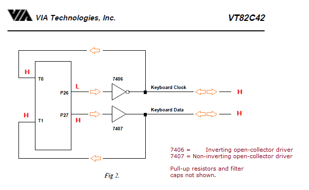
May be the DM7406N buffer circuit ?
It is possible that it is the Via VT82C42N controller, how can I test if the problem comes from the VT82C42N micro controller.
Thanks for your help.
I have an AP8548 socket 7 motherboard (80486DX2-S CPU at 66Mhz), the keyboard no longer works.
I can boot but the keyboard does not work.
I changed the 5 pin DIN socket, the fuse, there is indeed 5v in the DIN socket, I tested with several other keyboards, but the keyboard still does not work.
The battery is ok.
May be the DM7406N buffer circuit ?
It is possible that it is the Via VT82C42N controller, how can I test if the problem comes from the VT82C42N micro controller.
Thanks for your help.