• Please review our updated Terms and Rules here

ADC Super 6

norwestrzh

Experienced Member
Joined
Jan 11, 2021
Messages
86
Location
mount vernon, wa
My ADC Super 6 works great with the S-100 Computer Group's IDE/CF card as a "hard drive". Sixteen 8 MB "drives". One thing bothers me: I can't reset the Super 6. I've chased reset* around on the board, and it seems to go to all the places I'd expect (CPU, peripheral chips, etc.), but it won't reset the system. I have to power cycle it to do so. Any Super 6 users out there? If I had to guess, I'd say that there's a flip-flop on the card that only gets reset with a power cycle, but who knows?? Any hints greatly appreciated.

Roger
 
I just went thru the same symptom a few months ago. It ended up being capacitor C10. Change C4 and C10. They are both RC timers for reset. I think one is power on and the other is button.
Mine sometimes wouldn't boot at power up and not respond to reset button. Changing both those fixed it all. C10 is circled on the board photo.

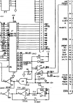
reset 2.PNG - Click image for larger version  Name:	reset 2.PNG Views:	0 Size:	68.9 KB ID:	1218818
 

Attachments

  • C10 circled small.JPG
    C10 circled small.JPG
    194.6 KB · Views: 1
Thanks!!! Can't wait to try this out. If this works, I owe you big time. I never would have found this on my own.

BTW, just to be rigorously correct: It is C9 and C10, not C4 and C10 (I agree -- it looks like a '4' on the schematic). The BOM with my documentation shows C9 and C10. C4 is a .1uf bypass cap on a 74LS04. I want to be sure that the info. is correct in case another ADC Super 6 user stumbles across this thread!

Roger
 
Yes you're correct, C9. I looked at my card and it's the cap right above C10. My photo was before I replaced C9. The schematic is horrible quality
I have a vacuum station and still had a hard time getting those caps out so only changed those two - C9 and C10. I remember mistaking that cap
the first time around for a C4. I had the card up on an extender and measured the voltage on C10 and instead of ramping up to 5V at power on it just
floated around at 2 to 3V so it was leaky, same for C9. I know techs say replace ALL caps but there's a hell of alot of them on this board and the
two slaves I'm running. It's been running great all summer. Here's a youtube of it running it's current configuration.

https://youtu.be/hU10bZ3igVM

Larry G
 
Hi Larry -- no joy! I replaced both C9 and C10 with brand new 4.7 uf tantalum caps. No change. System doesn't produce a monitor prompt at initial power on, but a power cycle at that point will get the monitor prompt. Everything seems normal from there, but if I ever have the need to press the reset switch, I get a hang. A power cycle will get the monitor prompt back. I checked reset at the Z80 and the SIO/DART and it goes low at both places with a press of the reset switch.

The old caps. both show ~4.7 uf with my DMM. Upon closer inspection, it appears that somebody had messed with those two caps. before. Evidence of resolder on the board.

Neat video of your system! I only have the CPU board (no slave gear), so something like that is out of my reach!

Roger
 
I pulled both C9 and C10 and spent some time probing the connections around the two of them. It seems to me that the silk screen is reversed for *both* of them! I'm not good at reading schematics, so I could be very wrong. On the schematic, it seems to me that the positive leg of both are facing each other? With that assumption, it seems to me that the positive symbol on the silk screen for both is reversed, and the positive legs should be toward the bottom of the board, not the top. Anyway, I soldered them in again in that orientation, and there is no change. So .... is it possible that one of the ICs around them, U14, U15, or U4, could have been damaged by the wrong polarity? Or maybe CR01??

Mystified.

Roger
 
yes the positive legs are facing each other. putting it in backwards wouldn't have damaged any chips since there are 27K resistors to the 5V line.
One thought, what are you using for a terminal ? Some terminals can be set to capture the reset to a local key.

Larry G
 
True -- no obvious damage to the nearby chips. I replaced them with new, and nothing changed. I'm using a Wyse terminal at 19.2k, but not using it for reset. I have a dedicated reset switch. It is functioning properly. I can see the reset working on the IDE/CF card, and as I said, I chased reset* around on the Super 6, and it is going low at the CPU and CTC with a switch press.
 
Still thinking out loud. Does the IDE/CF card have it's own boot rom? Manual reset will re-enable the boot rom on the ADC Master. Maybe there's a conflict.

Larry G
 
>> Does the IDE/CF card have it's own boot rom?

No, actually the IDE/CF card looks like an 8255 on the S-100 bus. I have a 2732 EPROM in the Super 6 that has some code @ F800 that starts up the IDE/CF card.

Roger
 
To eliminate the possibility of any sort of off-board conflict, I pulled all boards out of the backplane except the Super 6. No change in reset* behavior.

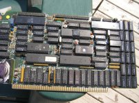
Here is a photo of my Super 6, in case it has been mis-jumpered?

sup6.jpg
 
There's a shit ton of jumpers and I'm checking mine vs yours. I'll look for more but I see your console is set to 19200 and mine is 9600. Also I'm running 4MHz cpu and dma, yours are both
6MHz. I recall having issues with lockup at 6MHz
 
Yes, I'm running it at 19.2k. Seems to work OK.

I think I saw something, somewhere, about DMA not working well at the higher clock. I'm not doing anything with DMA (or the FDC) at the moment.

I'm trying to understand what the difference is between reset* and power cycling the box. Maybe POC* is not being asserted with a reset? Should it be? Something I need to check. I am just guessing that something on the board retains its configuration when the power to it is maintained, but a power cycle resets and clears things?

Roger
 
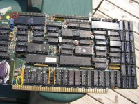
It looks like from the schematic that POC is not affected by reset but a low delayed by C9 charging at power on. The only other differences I see
between the jumpers on my board and yours is jumper P top left circled in red on mine is present on the left to pins like the rest. That affects the
parallel port settings but I wouldn't think matters at reset unless you have a printer attached. However, you are missing jumper E lower left circled
in yellow. Mine is on the lower two pins 1 and 2. That is an interrupt setting which if floating could matter during reset vs power on.
norwestrzh on vcf diff.jpg
 
No, no printer attached, so if the P jumper has anything to do with the parallel port, then it probably wouldn't do anything. I'm not using the parallel port at the moment.

I installed a jumper at E (1-2), and it doesn't change anything. If I can believe the schematic, E-2 is pulled high by RM5 in the absence of a jumper at E., so not floating?

I'm beginning to mistrust my monitor code (how it initializes the ports, maybe?). It is a modification of the old SD Systems Z80 monitor. What do use for a monitor? Anything? Or do you just directly boot up the O.S. from floppy? Do you know if a Super 6 monitor that is "official"? Can you point me to some monitor code that I could try out in place of what I'm using now?

Thanks for your interest in this problem!!!

Roger
 
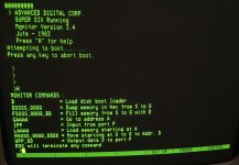
Well now, Larry -- this is pretty embarrassing!! I tried ver. 3.4 just now (it took some effort to "jiggle around" (technical term) my boot up code for the IDE/CF card), and it works! The Super 6 will reset properly from the monitor as well as CP/M, without a power cycle. I was surprised that the serial port ran at 19.2k (I expected that it would come up at 9,600). I poked around at some of the monitor commands, and they seem to work OK. I'm using a 27C32B EPROM, so I put my CP/M boot up code at F800h. I didn't want to mess with the monitor code at all before trying it out, so I have to start CP/M with a "GF800". I'm not terribly happy with that monitor because I would lose some functionality by using it. I have to take some time to study it vs. my old one (that wouldn't reset properly). Maybe I can figure out why mine doesn't work?

I didn't try the 3.6 vers., but near as I can tell, the only difference is the addition of a different boot medium?

Anyway, sorry for all the fuss. Turns out there wasn't a hardware problem after all -- just my lousy code. Thanks for all your help.

Roger
 
Back
Top