physicsrob
New Member
- Joined
- May 20, 2021
- Messages
- 3
Hi All,
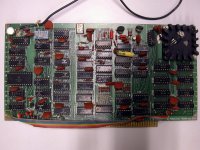
It's with great pleasure that I'm announcing a new S-100 board, a VDM-1 reproduction which I've been referring to as the VDM-2021. Now anyone can build a terminal-style text video card for the S-100 bus.
Details of the board, ordering instructions, and much more can be found here: https://physicsrob.github.io/vdm1/
The short history of this board is that I reached out to Lee Felsenstein to ask him what he thought of me reproducing the VDM-1. He was reluctant for me to reproduce the original PCB layout since the original layout had problems (like the ribbon cable), so he suggested I create a new layout for the original VDM-1 circuit. So that's what I did! Lee provided valuable feedback throughout the process.
Initially I will be selling the bare board for $30, or a partial kit for $90 which will include everything necessary to build a VDM-2021 that is not readily available through Jameco or similar electronics distributors. Specifically the partial kit will include:
- 1 x VDM-2021 PCB
- 1 x Character generator ROM (either MCM6574P or MCM66740)
- 8 x 2102 memory chips (equivalent to the 91L02 or 21L02)
- 1 x DM8131 bus comparator
- 1 x DS8836N bus receiver
- 1 x 93L16 binary counter
- 1 x heat sink
- 1 x BNC PCB connector
All remaining ICs are 74-series TTL or 4000-series CMOS.
This is my first S-100 board, and I'm doing this as a hobby, so a few disclaimers:
1) I haven't put in the order yet for the final production PCBs (I've had prototypes printed and I have assembled them successfully). I will most likely place the order in about two weeks, after gathering the initial orders, and depending on the response.
2) The hardest component to obtain is the character generator ROMs. I have about 50 ROMs available for these kits, but I have no idea yet if that's sufficient or way overkill. I believe I have a reliable source for more ROMs if necessary.
3) This is a hobby project, and I have a full time job, so shipping may be delayed, and while I will attempt to support builders, I can't make any guarantees of support.
4) While this board should be straightforward to assemble, this is not a beginner board. There are 48 ICs, and I highly recommend having a scope on hand to follow the integrated assembly-test procedure outlined in the original VDM-1 manual.
I hope you all find this valuable and enjoy! I've had a blast putting this project together, and it's very satisfying to use BASIC on my Altair displaying the output through a vintage monitor directly from this board. I'm excited to play Trek-80 as well, although I haven't gotten the keyboard working with Trek-80 yet.
Cheers,
Rob

