• Please review our updated Terms and Rules here

ECONORAM issues in IMSAI...advice needed.

Nama

Veteran Member
Joined
May 22, 2009
Messages
854
Location
New Zealand
Hi all,
I'm attempting to fix an ECONORAM 64k memory card in my IMSAI.

It basically exhibits some weird behaviour on the IMSAI data bus LEDs. Lots of random flickering, dimming, brightening, flashing etc:

https://www.youtube.com/watch?v=ujntZ4G3Jik&feature=youtu.be

This video doesn't quite show it at its worst, but it gives you an idea of what's happening.
I have also tried a 'known good' PSS RAM 16 card in the IMSAI, and that seems to work perfectly, so I think the IMSAI itself is good.

Before I start getting into the fix, I was just wondering if anyone had seen anything similar and had any advice.

Thanks

Phil
 
Last edited:
In that, case, this makes more sense :)

I have the 64K ExpandoRam running in an Altair 8800 and I've noticed that the data lights on the front panel remain on very dimly for zeros when the computer is stopped in front panel mode. This is due to the refresh cycles on the ExpandoRam. However, looking at your video, there's a lot more than this going on.

Is this a board that was previously working in the IMSAI or are you trying to get it to work in the IMSAI for the first time? If this is the first time, the ExpandoRam has numerous configuration options that must be properly set based on CPU type and other parameters - definitely not a plug-and-play board.

Mike
 
Thanks for the reply.
Good to know that the lights stay on but dimmed for zeros. That explains a little of what I'm seeing.
This board was previously installed in this IMSAI.

I played around a bit with it last night. Have quite a few spare IC's and one at a time I replaced nearly all the logic on the board (except 3 ICs which I didn't have). I also removed all but one bank of 4116 RAM chips.

What I have also noticed is that on the occasion when I can load something into a memory address, and then wait, I can actually see the bits flicker and change over a period of a couple of seconds. If I enter something into memory, and then move to another address, and return to the original address, that address in now empty.

I have looked at the voltages and I am getting around 12v and 5V out of the regulators, but I am getting -5.68V on the 4116 VBB pin, which is a little high, but not by much.

Someone mentioned that it could be a refresh issue, but I'm not sure what that exactly means, and how to go about fixing it.

Cheers
 
Last edited:
Hi All;
Nama, "" Someone mentioned that it could be a refresh issue, but I'm not sure what that exactly means, and how to go about fixing it. ""
Refresh is when and because You are using Dynamic Rams, and Basically that means that the Memory is a Cap, and it has to be Re-charged (Refreshed) or it looses it charge, hence it's memory.. I would from Your description say that is the problem..
If You have a scope look at the RAS and CAS signals they should be bouncing all over the place, If they are not, then I would look into that..
In these old systems I tend to stay away from Dynamic Rams and I use Static Ram Boards instead..

THANK YOU Marty
 
I have looked at the voltages and I am getting around 12v and 5V out of the regulators, but I am getting -5.68V on the 4116 VBB pin, which is a little high, but not by much.

I doubt it's the cause of the problems you're seeing, but I'd fix the -5v before proceeding with other tests. What does the -5v look like on a scope? Was this loaded or when no 4116's were installed?

Mike
 
Thanks for the replies

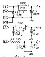
The -5.68V was read at the 4116's with all banks full, again with only one bank of RAM, and at the -5V source at C13 (see attached).

I'll break out the scope this evening and look at CAS, RAS and the -5V lines.

Thanks

EXPANDORAM POWER.jpg
 
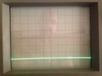
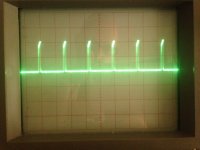
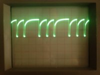
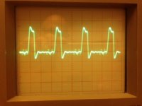
So here is what I'm seeing on the 4116 RAM:

-5V (2Volts/Div)
-5V.JPG
CAS (2Volts/Div, 2us)
CAS.JPG
RAS (2Volts/Div, 5us)
RAS.JPG

Is this any help???
 
Hi JDallas,
Thank you for the reply.
The Expandoram card that came with the IMSAI, and the card I'm trying to get working is an 'Expandoram I'.
I actually have an 'Expandoram II' that I got in a pile of S100 stuff some years back, but because of the amount of trace cutting and jumpering that would be needed to get it working in the IMSAI, I'd rather focus on getting the original working.

From what I can tell the the system was set up with the Expandoram occupying 48k (with the last 16k bank turned off), and a second WMC 8k memory card taking the total memory to 56k, and the last 8k then being occupied with some ROMs (I think for booting CP/M). Preliminary test of the WMC 8k cards seems to show it working.

I also have some other static ram cards that seem to be functional (although I have not tested them completely) that I could use in the system. 2x PSS RAM16 cards, and a Seals 8k card. These combined with the WMC 8k card could take the total memory to 48k. but that is a lot of chips, and a lot of heat, and a lot of stress on the 40 year old power supply, so I'd rather not go this route. Also from a cursory look at the contents of the ROMs in that last 8k, it seems that the machine booted a 56k version of CP/M, and I still have hope that those disks, which I have in my possession, still work.

Finally I have a PSS RAM65 card for which I can not find any manuals online, and I have not been able to get it working.

Thanks again.

Phil
 
Thanks again for the reply,
I can't imagine it's a configuration issue (could be wrong of course) as this card came installed in this machine, and in combination with other cards (ROM and the 8k RAM cards) makes me think it was working in this system at one stage.

Last night I poked around the EXPANDORAM board with a logic probe incase I could see anything obviously wrong.
Lots of random pulsing that matched the flashing of the LED's but nothing I could pin down.

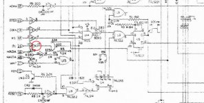
I did find something strange on U24 pin 10. Basically my logic probe shows high and low signals, but no actual pulse light. All other pins on U24 looked fine. U24 pin 10 goes to pin 1 of U14 (DM7425), which in turn connects to U9.
I looked at the input on U24 pin 11 (which connects to pin 25 of the S100 bus), and it’s pulsing high and low, and looks fairly normal on the logic probe.

I replaced U24 for another 74LS14, and it exhibited the same results…strange non pulsing signal on pin 10 again.
I even removed U14 incase it was causing some issues, and checked again with the same results. Not sure if I’m chasing a ghost with this one, as I can’t see any reason for the weird output on pin 10.

Will look at this again tonight.

U24 pin 10.jpg

Phil
 
Thanks again for your reply
I looked at the zoomed ExpandoRam (1) schematics 3 times and it looks like U24 pin 10 is an unused gate. I zoomed in on the address buffers and there were three with pin 10s in use, but no U24s.

Sorry, I'm not sure what you are saying here. U24 on my board is the bottom left most IC (SN74LS14N. A dual gate hex inverter)
Pin 11 is the input and comes from the S100 bus pin 25, and pin 10 is its output.
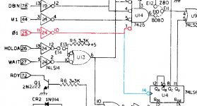
Pin 10 then goes to pin 1 of U14, as shown in the attached section of the schematic. Actually I have found 2 schematics, one shows it also connecting to pin 14 of U4. The other schematic shows a jumper here (E21 to E20) to make the same connection. My REV_A board does not connect to pin 14 of U4, and I'm actually struggling to find any E21 and E20 jumpers. Maybe this is a difference in the board revisions.
I have tested all these connections with a continuity meter.

The input from the S100 bus (pin 25), connects to pin 11 of U24, and shows a nice high/low pulse on my logic probe, but the output on pin 10 shows high/low, but no pulse!!! In the past, I usually assume the gate is faulty, but in this case if I drop in another 74LS14, pin 10 still shows no pulse, so either there is something else at play here, or I'm just confused.

Again, attached is the area of the schematic that I'm looking at. The red line shows the connections from the S100 bus through U24, and on to U14. The blue line is not connected on my board, and is actually consistent with the other schematic I talked about, so maybe ignore this.

U24 pin 10.jpg

Tonight I'll try to work my way through your other suggestions.

Thanks again
 
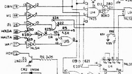
For completness, I have attached the same area from the second schematic which is slightly different:

Schematic 2.jpg
 
Looks that my REV_A board has no provision fjumpers between S100-25 (Phi 1) and the U14.
The jumpers I do have installed match those in the manual that set the RAM for 4116's.

I had to look up what Phi 1 was:
"Inversion" Of Phase 2 Processor Clock Line"

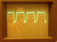
I broke out the scope again and had a look at pin 10 and pin 11 on U24:

Pin 10
U24_pin10.JPG

Pin 11
U24_pin11.JPG

Maybe it's all ok, and I was chasing that ghost again...what do you think?
Time to check elsewhere...
 
ExpandoRam Into IMSAI:

The way the jumper was drawn looked to be a IN-TRACE default jumper. In other words, no pins to jumper, just the trace on the back of the board so you can cut it if you really need to switch its connection.

Another thing I'd suggest is removing all the unnecessary boards from your IMSAI while looking at this DRAM problem. Using a MONITOR in EPROM would eliminate any likely DMA activity.

I suspect the problem comes down to the one-shots being out of spec. I was hoping the CHECK-OUT procedure would include testing those values, but it did not. No adjustments and 1970s fresh components and there was no reason for it to be tested.

I'll look over the ExpandoRam-I schematics seriously next Saturday afternoon, if not before then. I have a few SBC-300s, SBC-200s, ExpandoRams-* and I think an I/O-8 from my days as SD Systems - so learning about their prior designs doesn't hurt.

Rev A may be a challenge. The PDF is for Rev E. I'll dig in my paper SD Systems Manuals tonight and see what I have. As I worked on their last Generation III board set, I doubt I have anything that old. Anyhow, probably just introduced all the jumpers when they discovered it wasn't quite the plug&play design they originally thought it was. :)

- - - - - - -
Those jumpers can be installed in a way that tie two output pins together. Trace out all the jumpers that are connected to the path from S100-25 (Phi 1) inward. If there is a jumper in the wrong place, two outputs could be tied together.

- - - - - - -
I assume this configuration was bundled by a previous owner. That doesn't mean it was all working fine when he put it away and years later decided to give it a new home. It might also be that he kept another memory board and inserted that one to fill in IMSAI bus. With so many years that a system like that could have been in storage, the previous owner might not even remember whether the ExpandoRam was the right memory board for his IMSAI.

I'd suggest the first thing you to is document all the jumper setting on the board. There are a lot of ways to configure one of these boards wrong.

Check out the timing of U12 (a TTL Delay Line). I don't know how well those things age.

I also see a lot of dreaded one-shots on the board. The resistors and capacitors that establish its pulse width could easily be out of spec. My mentor at my first job said that the rule for digital design is: NO 555 timers, NO one-shots and NO monostable multivibrators... i.e everything should derive from an accurate clock signal.

User the ExpandoRam (1) manual, starting on page 7 through page 9, CHECK-OUT PROCEDURE to check the board out in the process of a check-out after build.

I recall that you previously wrote that you removed all but one bank of DRam for now...Note page 8 says, "*NOTE: If less than 32K is being installed on the board then refer to Section IV under ADDRESSING SWITCH to determine in which Bank the memory should be installed." Check that out in case there are some special configurations just for a single 16KByte Bank.

By the way, are you using a S-100 Board Extender? They caution not to use that during memory diagnostics... so that might be adding to the chaos.
 
JDallas,
Thanks again for all the great insights.
Didn't have much time to work on stuff tonight, but I did do two things however.
I replaced the tantalum cap in the -5V circuit. Unfortunately that didn't help bring the -5.68V down.

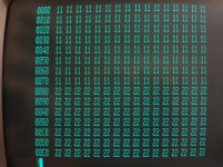
Secondly, I installed the Expandoram I card into my SOL-20. This gave me the option of using a monitor as you suggested to look at what was happening.

So this is what's happening:
Seems that when a byte is written, it effects a block 128 bytes long. For example (see attached) I entered 11h into address 0000h, and 22h into address 0080h.
You can see how it effects all 128 bytes...this seems consistent as you continue to move up the memory.

XRAM1_SOL.jpg

Finally, I have noticed that some 128 byte blocks turn to FF after a while. The 128 byte block starting at 0080 always seems to do this after a short while, whereas the 128 byte block starting at 0000h doesn't...that could be just bad memory chips???? I haven't played with it enough to know if there is any pattern.

Both these observations are consistent with what I was seeing on the IMSAI.

The Expandoram II is a total nonstarter in the SOL also, just displaying FF's in all member addresses, same as in the IMSAI.

...time for bed.
 
Again, Thanks for the reply. Yes, I'm positive I have the orientation of the cap the right way around.

Right now I'm thinking it may be in my best interest to find either a 16k, 32k or 64k SRAM board (bigger the better), and then I don't have to worry about these DRAM issues in front panel machines, and I could take my time getting the Expandoram card working for future use. I do have plans to build a system based on a SBC 100 board I have, and maybe the Expandoram 1 or II would be a better fit for this system anyway.

The IMSAI came and a dual 8" drive attached, with a small stack of 8" floppies containing various things, including a CP/M for 56k. My intention is to get the machine up to 56k (with the last 8k contain the boot ROMs) so I can try out the floppy. I already have two 16k boards, and two 8k boards, all of which seem to work in general, but probably have a few bung RAM chips to find, which SHOULD be relatively easy as I have done the process before on numerous occasions. On this subject, does anyone know if it's possible to boot 56k CP/M on a machine with less memory, say 48k? I know that when CP/M is relocated for a larger memory, many (some) of its components are shuffles around.

Anyway, I'm going to put the call out to see if anyone has a static RAM boards that I could purchase.
But in the interim, I'll order some diodes anyway.

JDallas, what do you think?

Phil
 
Back
Top