• Please review our updated Terms and Rules here

Altair 8800 Program Execution Not Working

Bungo Pony

Moderator
Staff member
Joined
Mar 31, 2008
Messages
617
Location
Winnipeg
So I'm back working on the Altair. The RAM is good, I can read & write to it, but when it comes to executing anything, it's not doing a damn thing. When I reset, all the status lights look good (MEMR, MI, and WO are lit). When I single step, the STACK LED will light up for the next two steps, and then it will go back to the way it was before. It will repeat the same pattern as long as I keep hitting step. When I go from examining address 0 and then hitting step, it will go to a random address each time. In other words, it seems to be completely ignoring anything in RAM, but it has the same execution pattern every time.

I'm not sure if there's more than one problem going on here with the CPU board, but I'm a bit puzzled as to where the problem would be.
 
W-10 should pulse to 1 if you do an EXAMINE
U-11 should pulse to 1 if you do an EXAMINE
U-8 should pulse to 1 if you do an EXAMINE
This forces a 0xC3 onto the bus as an instruction, this causes the CPU to load the addresses from U-11 and U-8 signals in sequence.

W-12 should pulse to 1 if you do any of the NEXT.
This forces a NOP onto the bus. The CPU increments the address.

Look for a pulse on MWRITE with a DEPOSIT.

Either of these should always stop in M1.

Has the Altair ever been working? If it was a kit there are likely a number of shorts on the bus boards
and on the front panel.
Also check that the connect from the front panel is oriented right for the 8 bits on the CPU board. It
can do a lot of strange things if not to the right pins.
Dwight
 
Last edited:
What boards do you have in the system. What does the CPU card look like ( and ROM? ) Is it a Z80 or a 8080?
Pictures?
Dwight
 
What boards do you have in the system. What does the CPU card look like ( and ROM? ) Is it a Z80 or a 8080?
Pictures?
Dwight

It's an 8080 CPU board Rev 1. The only cards I have in it are the CPU and the RAM.

I'll have to go dig out my scope so I can measure those pins. It might take a bit of searching since I recently moved.
 
Do check the data lines to the processor. It is not that unusual to see the connector upside down as there was no key to keep it correct. In other words D0 from the front panel goes to D0 of the CPU card and not D7, if the connector is swapped.
Dwight
 
Do check the data lines to the processor. It is not that unusual to see the connector upside down as there was no key to keep it correct. In other words D0 from the front panel goes to D0 of the CPU card and not D7, if the connector is swapped.
Dwight

I know the connector is correct. I had to repair a couple of those wires along with a trace on the front panel from someone who left the soldering iron on it a bit too long.

I found my scope, but the leads for it are currently MIA. I might just say screw it and patch something together.
 
It is beginning to sound like a problem that will need a scope. I just helped get one working that had about 1/2 dozen original solder bridges between the front panel and the bus boards. You might just go through things with an ohm meter on the bus boards first.
For a 1X scope probe, a piece of coax with the bnc on the end is not all that bad. The wave form will not be clean but it will work.
Dwight
 
I finally found my scope probes. Now to proceed!

W-10 should pulse to 1 if you do an EXAMINE

It does

U-11 should pulse to 1 if you do an EXAMINE

It does

U-8 should pulse to 1 if you do an EXAMINE

It does

W-12 should pulse to 1 if you do any of the NEXT.

It does

Look for a pulse on MWRITE with a DEPOSIT.

It does

It deposits data into RAM fine. The problem is when I'm executing anything, either with the single step or run. I will check the bus lines. I went through them and didn't find any shorts, but I'll check the bottom of the board anyway.
 
I went through the bus connectors and found that whoever soldered all this seemed to have a lack of solder on many of the pins, so I filled them all nicely. Didn't find anything really critical other than that, but I'm still having problems.

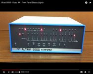
So this is what I'm seeing on my Altair. I followed along with the video here that is supposed to test the status lights. The program listing is here. The program correctly remains in memory even after execution, so I know all of that is working fine. When I single step, I'm supposed to get this:

altairshould.jpg

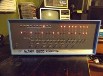
Instead, I get this:

altairnot.jpg

It's an absolute mess
 
My best guess is there's something wrong on O-2 or O-3, meaning that it could be IC-O itself or perhaps the 8080. Honestly, I don't think it would be the 8080. I've checked over the lines, re-soldered the connections on the 8080 socket, re-soldered all related ICs, and it hasn't helped.
 
You might check that the single step only makes a single fast pulse on the S100 pin 21. I'm thinking it may be the bus buffers that read data into the 8080 from the bus that isn't working correctly. Notice that the high and low parts of the address look similar. This is a possible problem on the CPU card. The functions of the front panel should be unaffected by the input buss buffer on the CPU card. Reading from RAM into the CPU use ICs O,R,F and H, of the CPU card. You should see, one or more, pulse at the enable pins of F chip on the CPU for the single step. This depends on what instruction the CPU see. You might also look to make sure that none of the enable pins used for front panel pulse at the same time that might cause contention with the data coming into the processor. You know, the ones that jam the C3 or address bytes. If the front panel jammed a C3 at the same time as executing something from RAM, it could send it off to never never land. Single step only does two things. It releases the ready signal for one cpu execution cycle and enables the data in from the S100 bus by pin 21 of the S100 bus ( goes to the bus buffers on the CPU card ). The data signals buffered from DI0 to DI7 is the only thing that is different from what you see on the display of the front panel and what the CPU executes when run or single step. When doing other front panel operations like loading data or address, that buffer is disabled. Only when the CPU is actually executing instructions from the RAM is the buffer enabled. A bad buffer, missing enable or interference from one of the front panel drivers could cause it to go wacko.This data is driven by those buffers to the CPU from the S100 RAM data.
That should give you some places to look.
Dwight
 
Last edited:
The CPU card has been the prime suspect with almost all the problems I've encountered with this Altair. I've already replaced other blown parts on it. The only thing I've found wrong with the front panel was a couple of pads that someone scorched off the board by leaving a soldering iron on them for too long.

I'm out of town for work this week, so I won't be able to get to troubleshooting until I'm back home. Thanks again for your input.
 
The stock Altair CPU board had a marginal clock circuit. I suggest that you take a close look at the 2-phase clock signals. Remember they must be non-overlapping. Any noise or skew with the two phases can make them overlap and cause problems.

smp
 
It could still be the front panel, if it were jamming the C3 during the bus read of the instruction. It is not as likely as the buffer or the SS pulse.
To try to get an idea if the buffer is working at all, you might put some 00H in the memory and single step through them. If something like the C3 is being driven by the front panel the buffer should override the C3 to all 0's and do a single address step. Another thing to try is to do a 0FFH. that will do a RST 7 that will go to address 38H. If the buffer isn't working at all, it could go almost anywhere.
Anyway, those two instructions should give you more insight into the problem.
Dwight
 
Hi all;

What that looks like is that even though You have the 8 pin connector connected, it might not be passing any signals through, from a possible thin film or corrosion on either the pins or on the female connectors from age..

THANK YOU Marty
 
IC0 on the processor board is a possibility as well as the data in buffers ICF and ICN. The only difference between front panel operation and running from RAM is the fact that the data bus to the processor should be driven by the S100 bus. Running the front panel is local instructions to the CPU and data bus is read to front panel light off the data bus.
Did you try using the FF or 00 data for single step yet? If it is a single driver in ICF or ICN, you should see one of the two execute properly ( most likely FF that would work ).
Dwight
 
Back
Top