• Please review our updated Terms and Rules here

IMSAI 8080 Frankenstein machine ?

zippysticks

Veteran Member
Joined
Nov 21, 2017
Messages
574
Location
UK, South East
Folks,

I have taken an expensive plunge and bought this IMSAI 8080 machine from via Ebay.
It looks like it has been apart a lot and hasn't really been put back together properly.

Discounting its obviously wrong steel cover - I'm looking at a replacement from the folks at imsai.net - I can see a few challenges with this unit:

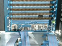
It has had a TinkerToys Wunderbuss Noiseguard S100 backplane installed. This would appear to be an 18/20 slot backplane. I can find details of these boards up to 12 slots but does anyone have any details for this larger model ?

The other thing that looks odd is the power supply - I don't recognise much beyond the transformer type it is using - a Tranex 4-3751.
This does appear in the BOM for the IMSAI PS-28D unit so I"m assuming is original. I would have preferred the Tranex 4-3819-1 used in the PS-28U for use in the UK as it is capable of being configured for 240V input.
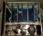
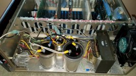
Does anyone recognise this PSU layout - is appears different from everything else I have seen and doesn't seem to make use of a PCB mounting to house the components. Instead the major components (transformer and caps) seem to be mounted to the chassis and then fed to the rectifiers etc. on a small board mounted behind the front of the chassis.

As this machine is not working, the plan is to disconnect everything that has been done before and rebuild working through the power supply to start with.
I have variac that I can use to to test the power supply once it has been rebuilt - any other advice appreciated.
s-l1600.jpg

s-l1600 2.jpg
 
Last edited:
s/TinkerToys/ThinkerToys/

> I can find details of these boards up to 12 slots but does anyone have any details for this larger model ?

The original 1977 WunderBuss only has active backplane termination, the 14 slot is called WunderBuss IO
and the manual is on bitsavers.
The termination circuit should be the same on both.

dscf0101.jpg

Herb has an 18-slot schematic if you really need it
http://www.retrotechnology.com/herbs_stuff/d_morrow.html
 
s/TinkerToys/ThinkerToys/

> I can find details of these boards up to 12 slots but does anyone have any details for this larger model ?

The original 1977 WunderBuss only has active backplane termination, the 14 slot is called WunderBuss IO
and the manual is on bitsavers.
The termination circuit should be the same on both.

View attachment 53715

Herb has an 18-slot schematic if you really need it
http://www.retrotechnology.com/herbs_stuff/d_morrow.html

re. ThinkerToys/TinkerToys - thanks for pointing out although I think the latter is more appropriate in my case !

Thanks for the steer on termination - if its the same circuit regardless of slot count then any of those docs should cover it I suppose.
 
There was a fellow, recently, that was asking about correctness of his power supply connection. His looked to have the same separate PC board arrangement as your machine has. I would say it was a later improvement made by IMSAI. My machine is an older one with the long PC board in it.
I always recommend forming the capacitors with a series resistor and a variac but I'll admit I don't always follow my own advice. You should be fine with a limiting current of less than 1ma leakage. These are computer grade capacitors and should tolerate that much and more while forming. You should disconnect the load with the resistors in series with the larger capacitors as it will significantly increase the ripple current on board bypass capacitors before and after the regulators. You want to have about a 1V to 2V drop on the resistor for that current, when selecting the resistor values..
Let the voltage soak a little while in steps, even with the resistors. I'd recommend 0.5V step soaks for about 12-24 hours until you reach at least 2.5V, on the capacitors, or so. The capacitors tend to degrade in pit like locations and not evenly. This means the forming will tend to concentrate the current in small spots. You don't want to over heat the small spots.
Dwight
 
I believe that's the PSU configuration from early machines. The large circuit board came later. My machine is S/N > 17,000, one of the last, and it has the PS-28 supply.

From IMSAI.net / Todd Fischer:

The Power Supply- The first IMSAI's used a 10 amp power transformer, the PS-A choke/filter board, and rectifier/heatsink assembly (mounted to the rear of the front sub-panel). Two large electrolytic "can-style" capacitors were held to the base plate with circular clamps and connected to the rectifiers with ring terminals at the top screws. Connected in parallel, they provided filtering for the unregulated 8 volt DC supply, while two smaller axial lead electrolytics mounted on the PS-A board filtered the unregulated plus and minus 18 volt supplies. I estimate between 100 and 200 of these machines were shipped; a few languished in Engineering, Marketing, and Customer Service for a year or so before they were scrapped.

In early 1976, a new 28-amp power supply dubbed the PS-28 became standard issue, incorporating a TRANEX power transformer and 16 1/2" x 5 3/4" power supply board. This cumbersome arrangement included three line chokes, ceramic line filter caps, rectifier/heatsink assembly, two 80,000 mfd. and two 10,000 mfd. electrolytics that were now mounted to the PS-28 board with the screw terminals in contact with the board. A fuse clip arrangement provided for short-circuit protection. Sadly, the whole arrangement of line voltage layout was a dangerous design exposing the builder and user to potential shock in the area of the fuse clips, power switch, chokes and several other areas.

https://www.imsai.net/support/first_imsai.htm
 
I believe that's the PSU configuration from early machines. The large circuit board came later. My machine is S/N > 17,000, one of the last, and it has the PS-28 supply.

The serial number of my machine is 001962 - not sure whether that is a low (presumably older) number or not.

According to the user guide for the PS-28U and PS-28D , the Tranex 4-3751 transformer in my machine is the same as deployed in the PS-28D which can supply 28A for the 8V supply. But my PSU does not have the same layout as the supplies in that document but does sound s little like that description you provided in that link.

https://amaus.net/static/S100/IMSAI/system/IMSAI%20PS28U%20Power%20Supply.pdf
 
Last edited:
There was a fellow, recently, that was asking about correctness of his power supply connection. His looked to have the same separate PC board arrangement as your machine has.

Ah, found that thread here - thanks.
http://www.vcfed.org/forum/showthread.php?69197-IMSAI-8080-need-wiring-verification-on-PSU-section&highlight=imsai+8080

That certainly looks like my layout - perhaps I'm not alone (unless I have just bought his ! There can't be THAT many 8080's around San Jose/Livermore can there ?)
 
Last edited:
Todd's site is the reference for IMSAIs. I was mistaken about my machine.
It would seem that the OP's machine is in fact an earlier machine. I was basing it on the earlier disk setup my machine had. My machine could have been upgraded but I think my setup had its original configuration of the later power supply, making it a later machine. The serial number tag is long gone from mine.
Dwight
 
Congrats on the purchase and welcome to the IMSAI club!

As has already been mentioned, you have the earlier version of the power supply. Luckily you have the Tranex transformer which is compatible with 50Hz mains. When I bought mine from the US, I had one of the earlier 60Hz only Signal Bel transformers. I ended up carefully removing the PSU from mine and fitting switch mode PSUs instead.


The Power Supply- The first IMSAI's used a 10 amp power transformer]

That's actually a typo. From an email discussion with Todd Fisher the other year...

"The 10 amp spec is an error. There was the original 20 amp supply that used a Signal (brand) transformer, the rectifier board mounted to the back of the front subpanel, and capacitors mounted directly to the base. That was the PS-A. The later PS-28 had all components including transformer mounted to a long circuit board. That is the 30 amp supply that lasted throughout later production. "

There was also a dual PSU option offerred which combined a pair of PS-A's to provide upto 40 Amps.

Cheers,
Dave
 
That's actually a typo. From an email discussion with Todd Fisher the other year...

"The 10 amp spec is an error. There was the original 20 amp supply that used a Signal (brand) transformer, the rectifier board mounted to the back of the front subpanel, and capacitors mounted directly to the base. That was the PS-A. The later PS-28 had all components including transformer mounted to a long circuit board. That is the 30 amp supply that lasted throughout later production. "

Now that makes sense! I wondered about that 10A value.
 
It seems this is the same machine from the other thread

http://www.vcfed.org/forum/showthread.php?69197-IMSAI-8080-need-wiring-verification-on-PSU-section&highlight=imsai+8080

I hope I have more luck getting it going than the previous owner.

I'm not sure how I lost track of the other thread. I see he'd last posted on April 30th? I suspect he'd plugged it in with the resistor in series with the input. I suspect the resistor was a 2K but don't know as it isn't clear. That would not be enough to protect the rectifiers from a dead short. I can't see from the angle of the picture but I suspect the rectifiers are a pair of stud mounted type diodes. One or both may be shorted ( or open ), if powered on with the resistor on the primary.
If the diodes are shorted they can damage the capacitors( if you connect the wires up properly now ). If the diodes are a pair as I believe them to be, you need to unbolt them ( assuming they are stud mounted ) and check each individually ( the windings of the transformer will make them look short if in circuit or at least in parallel ).
The larger capacitor, of the pair, has been replaced. That may be an indication of an earlier shorted diode.
Don't do any supply test with the front panel connect to power through the mother board or you may damage it as well.
Let us know when you get your hands on the machine.
Dwight
 
Great advice - thanks Dwight.
I plan to be quite methodical with this machine - I just hope it hasn't already been significantly damaged.
 
Back
Top