dfnr2
Experienced Member
It took a while for me to get back to this, but I have built up and verified the new module.
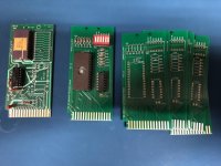
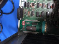
Here's a photo of the board, along with my original peronality module.


I've loaded a 27C64 with the ROMs from the SOLACE emulator: SOLOS, CONSOL, SOLOS (v2) and DPMON.
All seem to boot, but keyboard issues keep me from testing them.
I'm working on a new rev which will address some issues. I could use input from you guys.
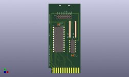
1) The resistor spacing is too small for regular 1/4 W resistors. I had some 1/8W 10K resistors, which will work just fine--these don't pass much current. I've also seen mini 1/4w resistors which are available from Digikey and Mouser. The new rev (on GitHub) increases the spacing. However, I'm tempted to just replace these with a ressitor network.
2) I am using a 6-wide DIP switch. In my case, I used a Dremel to cut off 2 switches from an 8-wide DIP switch. To avoid requiring a 6-wide DIP switch, I'm changing the switch to a 0.1" 2x6 (or so) header, with jumpers to configure the PCB. This will be easier and cheaper to source, can be cut from a long header, and is easier to understand the configuration, since it may be hard to tell if a switch position is open or closed.
3) I included a switch to enable or disable the C4xx ROM block, in case someone with a 1K ROM decided to put something else at C400, but I doubt this is useful, and requires a switch to be closed, or a jumper to be placed. I'm planning on removing it from the next revision.
4) This board should be compatible with 28C256, 28C128, 28C64, 27C128, and 27C64 (which I used because that's what I had). The 27C256 won't work because of different mapping of a couple of pins compared with 28C256. If I move to a 0.1" header for configuration, it will be easy to add a 2-position jumper to select between 27C256 and everything else.
5) For the Cxxx->Fxxx remapping, a couple of jumpers must be placed between the main board and the module. The pins on the "A" side are all easy to access without removing the main board (which is a project), but they are all used. This version uses pins B2 and B3, which are apparently used for programming at the factory. But, they are hard to access without extensive disassembly. I'm considering just bypassing the connector, since the personality module is basically only providing a switch. Instead, I'm thinking of bringing a pair of wires from the motherboard to a 2-pin 0.1" socket, which can be routed along the side of the case to a switch, or plugged into two shoted pins on the 0.1" header on the personality module. For no remap, the wire could be left unplugged, or for neatness, plugged into a pair of open pins on the 0.1" header.
Or, just require disassembly and accessing the underside of the main board to do the remapping mod.
Any thoughts?
BTW, if anyone wants one of the blank PCBs, let me know.
The design (in progress) is up on GitHub: https://github.com/osiweb/Hardware/tree/master/new/sol20/personality
Dave
Here's a photo of the board, along with my original peronality module.


I've loaded a 27C64 with the ROMs from the SOLACE emulator: SOLOS, CONSOL, SOLOS (v2) and DPMON.
All seem to boot, but keyboard issues keep me from testing them.
I'm working on a new rev which will address some issues. I could use input from you guys.
1) The resistor spacing is too small for regular 1/4 W resistors. I had some 1/8W 10K resistors, which will work just fine--these don't pass much current. I've also seen mini 1/4w resistors which are available from Digikey and Mouser. The new rev (on GitHub) increases the spacing. However, I'm tempted to just replace these with a ressitor network.
2) I am using a 6-wide DIP switch. In my case, I used a Dremel to cut off 2 switches from an 8-wide DIP switch. To avoid requiring a 6-wide DIP switch, I'm changing the switch to a 0.1" 2x6 (or so) header, with jumpers to configure the PCB. This will be easier and cheaper to source, can be cut from a long header, and is easier to understand the configuration, since it may be hard to tell if a switch position is open or closed.
3) I included a switch to enable or disable the C4xx ROM block, in case someone with a 1K ROM decided to put something else at C400, but I doubt this is useful, and requires a switch to be closed, or a jumper to be placed. I'm planning on removing it from the next revision.
4) This board should be compatible with 28C256, 28C128, 28C64, 27C128, and 27C64 (which I used because that's what I had). The 27C256 won't work because of different mapping of a couple of pins compared with 28C256. If I move to a 0.1" header for configuration, it will be easy to add a 2-position jumper to select between 27C256 and everything else.
5) For the Cxxx->Fxxx remapping, a couple of jumpers must be placed between the main board and the module. The pins on the "A" side are all easy to access without removing the main board (which is a project), but they are all used. This version uses pins B2 and B3, which are apparently used for programming at the factory. But, they are hard to access without extensive disassembly. I'm considering just bypassing the connector, since the personality module is basically only providing a switch. Instead, I'm thinking of bringing a pair of wires from the motherboard to a 2-pin 0.1" socket, which can be routed along the side of the case to a switch, or plugged into two shoted pins on the 0.1" header on the personality module. For no remap, the wire could be left unplugged, or for neatness, plugged into a pair of open pins on the 0.1" header.
Or, just require disassembly and accessing the underside of the main board to do the remapping mod.
Any thoughts?
BTW, if anyone wants one of the blank PCBs, let me know.
The design (in progress) is up on GitHub: https://github.com/osiweb/Hardware/tree/master/new/sol20/personality
Dave


