• Please review our updated Terms and Rules here

Imsai 8080 cannot examine to RAM adress...

Jan1980

Experienced Member
Joined
Mar 13, 2015
Messages
72
Location
Germany
Hello.

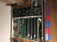
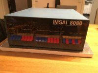
These days i´´ve got an Imsai 8080 in an optical great condition. It is one of the first versions with exp-22 motherboard but it had only 10 sockets. And it has the old Signal transformer 8063-A. I think, this is 10A version ?! I don´t know.
Ao, i checked the voltages with oscilloscope, everything fine. I tested the small testprogramm.

IN FF
OUT FF
JMP 00h

I think, this is everybody´s first programm on imsai with toggle switches ?! It works.

I am using 64kb of RAM. I mounted 2 32kb salota mixed memory cards to the boards. The boards are tested and i bought them from a friend here in germany. But i´ve got a problem. There are the 16 switches, when i switch 11110000 00000000 and press examine, the it should jump to memory adress F000 and the first four of the 16 LEDs should be on. This does not work !
I removed the frontpaned and cleaned everything, i removed the cpu card and cleaned everything. Some of the logic chips in front panel i checked with my chiptester successfull.

Do you have an idea ?

THX

Jan
 
When the processor is stopped, things are static. The processor is halted and the data on the address buss is static. This means you should be able to trace most problems with a meter. At worst a logic probe with a pulse detector.
I don't know how much you know about the way the IMSAI and the ALTAIR front panels work. Both work basically the same. When you enter an address there are a number of open collector buffer ( 7406 as I recall ). These do 3 thing in sequence. First they jam a C3 onto the processors data bus. The processor sees this as a JUMP instruction. It then expects to see the address on the next 2 memory cycles. These are provided from two other sets of 8 open collector buffers, on the front panel, that go through the address switches on the front panel. Since you were able to enter a program, I'd suspect that this is mostly working. You should see any address you enter from the front panel on the processors address line as a static level, easily read from a meter.
The next thing to do is to put all of the address line high and see which address lines if any are working. Also, try some other combinations. We need to see what works and what doesn't. The fact that you were able to enter an sequence of address from reset doesn't tell us anything about entering addresses. Any of the stepping functions just jam a NOP instruction onto the CPUs data buss and it just sequences the address. The front panel is not generating that address, the CPU is.
You see, it isn't really the front panel doing all the work. The CPU is creating the address, on the bus, while the front panel only tells the CPU to go to that address and the CPU creates the address. We need to determine if the address isn't getting from the CPU to the address buss or the front panel's address isn't getting to the CPU.
So please try some other addresses so we can see which bits are missing.
Use care when handling things if you have the AC switch on the front panel. Put a couple layers of insulating tape over them to keep from making sparks or killing your self.
Dwight
 
Thank you ! I have tested logic chips in examine circuit. All 74123n are damaged. I cannot believe. I tested with expensive elnec beeprog2 programmer. I can test 74123 but there is not writtem 74123n. All habe them same error. What is the meaning of the n in 74123n. This means negative ?
The 74107n is also damaged says my programmer. I think, i have to doublecheck with logic probe and oscilloscope.
Btw, i tried different ram cards, always the same.
So, you think, there could be also a problem with cpu card ?

Thx

Jan
 
The N suffix in the 74123N part number just means it is a PDIP package. A D suffix part number would be an SOIC package.
 
It is possible that the 74123s are bad but on analog timing parts, I would not trust a static logic tester. As gslick says the N is a package type indicator is not a negative indicator. As a general rule, I don't trust logic testers as they do not actually test the part at real speeds. I prefer to diagnose the problem first. These testers just do a static test. If it says the 74107 is bad, that is more likely bad, unless the tester has a bad setup for that particular part.
When we ask to run a test, we'd like to hear the results. Many of us are good troubleshooters and we can help a lot with finding problems. You are our eyes and ears. We like to hear I did "this" and the unit did "this".
Still based on your results, I'd replace the 74107 first. 74123s are notorious for failing but I'd not replace them based on a simple logic tester.
As far as, is it the CPU or the front panel, we do not have enough symptoms yet, that is why we ask for test.
Dwight
 
Last edited:
You have said that you did the I/O test. That means the Deposit Next is likely working. That would indicate that the CPU was not the likely failure.
Dwight
 
So, i tested with logic probe and your great schematic.

U23 74123:

Voltage supply 5.22 V ok
Pin 9 high while examine
Pin 7 pullup 5V ok
Pin 15 pullup 5V ok
Pin 6 to pin 7 capacitator nearly 100nF ok
Pin 12 Signal ok


U13 7402

Pin 11 signal from U23 ok
Pin 1 low in direction U18
I swapped this chip for trying, not works

U18 74107

Pin 12 signal from U13 ok
Other measurements in examine circuit on this chip not working, so i have to swap.

I have no 74107 chips in stock, so i decided me to order all of the logic chips in front panel for reserve. I think, a new 74107 will fix the problem ?! I let you know.


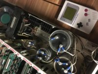
Can you tell me something about the power supply with signal transformer ? My Imsai has serial number 1258. Is this 10 Ampere version ?

THX

Jan
 
What I asked for was do any of the address light go high when you try to examine them with the switches high. I'm trying to determine where to begin looking?
I don't know from the serial number which supply you have. A picture of the capacitor area in front of the transformer will tell if you have the newer or older supply. The newer supply with the higher current has the capacitor's screw terminals directly attached to the power supply PCB. The older type of supply has the screw terminals facing up and wires connecting the capacitor's terminals.
Dwight
 
This is an older IMSAI that has been upgraded with bigger rectifiers and bigger capacitors. The transformer looks to be original but I'm not sure.
It doesn't need a video, just something like "examine doesn't light any of the address lights when I have the address switches up" or "It failed only for the top 4 address lines" or something like that. All we know so far is that it doesn't work for the 4 highest address bits. There are many possible issues that can cause this. If it does work for any address bits, the 74107 is a likely suspect but not the only one. Also likely if only the lower 8 address bits work but not for the upper 8 address bit.
So you see, different problems sources produce different results. Trouble shooting is about running experiments and seeing how it is failing. Using a logic tester can be useful but as you see, it can also give false results as with the 74123s. We know that half of U17, half of U23 and associated circuitry are working because you were able to enter the port program. I've never use one of these testers as I've never needed one. I see it as a shotgun approach.
Looking at what does work and what doesn't is how trouble shooting is done. Often, removing all the socketted parts to test them, causes a component to have a folded lead or getting the part put in upside down. Now one has two problems to fix. You see, by ripping all the parts off the board, you could have damaged them and been no closer to solving the problem.
Analyzing the failure and then using the tester to look at the suspected part is the proper way. You see, the problem we've seen so far could have been shorted address lines on the motherboard bus. It could have been bad 7405's on the front panel. It could have been bad address bits in the buss drivers of the CPU card or any number of possible failures.
Trouble shooting on the message board can be slow but it can also be a learning experience. It can take weeks to find a problem that in my hands can be isolated in minutes. Still, one can develop the proper way to use the symptoms to analyze the cause. It also was an opportunity to learn how the front panel of a IMSAI works so the next time something doesn't work right you'd have developed the methodology to trace down the issue.
Dwight
 
Hello.

Yes, you are right, i´ll try to describe again. My Imsai has only the cpu board and 2 cards "salota mixed memory". It has 64kb RAM. When i start the imsai, then i press the four switches on the left side. After pressing examine, the LEDs on the top of the switches shoold be on, the computer should jump to memory adress F000 in this case. This does not work. But, the little testprogramm from owner manual works fine. So, deposit and deposit next work, but examine not working. Examine next works, too. Only examine without function. I made 2 videos. Please take a look. You can see the result. I tried to examine different memory locations.

Examine not working:


THX

Jan
 
This is why it is important for you to tell what you did and the result. If you'd said to me, "When I hit the examine switch, with the address switches a F000, the address goes to 0003" and then "When I hit it again, it goes to 6", we'd have had some useful information. ( what I did and what it did !!!!! ). You see it did do something. The address looks to sequence by +3. That is important information. That of U18 working correctly. At least output pins 2 and 6 have to be working right or we'd not get the wait light from the chip counting from 0 to 3. The wait works if the counter has Q0\ and Q1\ at 11, U14 will have 0 on pin 8. this blocks the PSYNC signal from the processor from getting to U18's clock input and puts a 1 on U15's pin 6. Since all the other functions are waiting, all the input to U21 are also at one. The output of this NAND gate is 0 or no XRDY. This puts the processor in hold, waiting for the next input ( note the WAIT light ).
When you push up the examine switch, it creates a clock pulse on U18 and it sequences to the count 01. This should sent the C3 ( C3 is the JUMP instruction ) data to the processor ( note the bubble with the C3 in the schematic ). Since now, the counter U18 is no longer at 00 ( remember U14 ), XRDY it now high and the processor is running and fetching data. It wasn't getting a C3 as we thought we were sending it. Instead, it looks like it was getting a single byte instruction but the XRDY still allows it to fetch another instruction because the counter U18 has not count back to zero. A two bit counter only has for states. 00 is wait, 01, 10, 11 are XRDY high so for three instructions, the processor fetches.
We know that the low order address/data bit switches are working but it looks like the C3 is not getting to the processor.
This is where your logic probe can now come in handy. We know the Q\ outputs, on U18, are working because it allowed the processor to increment the address to three and then set it to WAIT.
We don't know if the problem is the Q pins of U18, U12, U11, U6, U4, U1, U7 or U3 ( or some other I didn't look at ).
First I think it would be good to run a little experiment.
We think the sequencer ( U18 ) is working because we were getting the count of 3 on the addresses. It looks like we were not getting the C3 to the processor. We should be able to get the processor to see an instruction on one or two of the fetches of the address. We should be able to trick the processor to tell us what it is seeing instead of C3, depending on how much is working. If it is one of the 7405s failing this should help us.
What we can do is set the low address bits to 00000000 and the high address to 11000011 ( C3 ) . On the first switch of the EXAMINE, it should see the C3 and be waiting for
rest of the two address bytes. If we now set the high address bits to 00000000 and then hit the examine once, it should do the jump to address 00000000xxxxxxxx and then sequence once more to xxxxxxxx+1. Note that the processor would think that the first part of the sequence that was suppose to be C3 was the low part of the address, xxxxxxxx.
Remember, it is not the switches that are the address on the lights, it is the address that the processor outputs. The processor should read the first set of 7504s as the low address. When it reads the high address, it will increment it once.
Lets give this a try and tell me what you get. ( remember "I did this and I got this" is the answer I'm looking for, OK. Remember you are my eyes and ears ).
 
This may not work. 11110000 from the first test would be interpreted as Retrun if positive ( or RP ). We didn't see any funny operation when you had F000 for the address.
If the above doesn't work , we can try a similar test but this time use the low address switches to do a C3 instruction.
Again, "I did this and it did that" for both test.
Dwight
 
Hello.

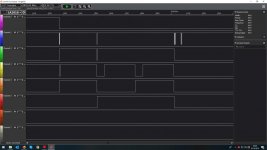
Today, i had time to check something. I connected my logic analyzer to the data bus. When i examine always FF. There is no C3 or anything, you are right. Everything is coming at the same time. There is no counter who make c3, then 00, then f0 for example. All databus pins on cpu are in high state. When i press examine, there are all together to low. I checked voltages on the logic chips and so on. And i try to check every logic chip with probe at the moment.

THX for your help !

Jan
 
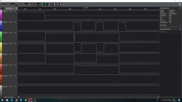
So, please take a look. I tested with my logic analyzer the pins from the small graphic in the schematic. Looks like there is a problem with psync ?!

imsai_no_examine1.jpg
 
Sorry, i was on the false pin with psync. I have to say, i bought the logic analyzer before a few weeks and it´s the first time to work with it.. :) I´ll now check again the databus. Psync goes from low to high and not from high to low. What do you think about that ?

imsai_no_examine1.jpg

So, C3 and the MSB and LSB are there. I think, there is something wrong in the 8t97 area ?!

THX

Jan
 
Last edited:
I'm not sure your grabbing the right pin for PSYNC\. Not a big issue as I think the problem is elsewhere.
U18-12 should track PSYNC\ and it looks like it is doing the right thing at U18-12. I don't know how it could without a correct PSYNC/
Since U18-12 looks good lets look elsewhere.
Can you leave a probe U18-12 and sync there and put three channels on:
U10-12
U12-8
U14-6
This will check the count decoder so we can see if it is the decoding that is failing or the 7405s. Many have had trouble with them.
If it is the decoder, I'd be surprised but in these old machines, nothing really surprises me.
My friend bought a Altair that was said to have worked once. Besides the typical broken wires from the front panel ( solid strand without proper strippers is a sure failing point ), there were 4 solder bridges on the data and address busses. It is not likely to have ever run that way.
Anyway, with your analyzer, we should see a series of single pulses in order.
Dwight
 
Back
Top