• Please review our updated Terms and Rules here

IMSAI 8080 SIO Rev 3

Novell2NT

Experienced Member
Joined
Apr 3, 2016
Messages
194
Location
Palm Coast
I have just finished reading the users manual for the IMSAI SIO board. I have to tell you, the manual does not clearly state how many of the jumpers should be setup.
particularly things like setting up the baud rate. Stop bits, full or half duplex.

I could use a lot of help with setting up the SIO board, so that I understand what I am doing and why. I do have some experience doing some simple assembly programming to
access the SIO board on my Altair, but the documentation was put together a lot better.

So I have a basic understanding of the Output and Input functions as well as the Control Byte and Status Byte.

I currently have two boards, that were already jumpered, but I can not make their configurations out, but really it does not matters, as I am sure that neither one of them is configured
the way that I might want them to be configured. Which is one port for a terminal and the other as a file transfer port.
Although I would like to understand how and why these two boards were configured the way the were. My best guess is one was setup for a current loop for a TTY device and one may have
been setup for a modem on one of the ports.

I will upload some pics as soon as I am able to.
 
You need to look at the data sheet of the UART used on the board. See:
http://www.bitsavers.org/components/gi/_dataBooks/1977_GI_Data_Catalog.pdf
page 348 for, I believe it use a AY3-1015 or similar.
There were other manufactures of these parts but there was no standard numbering system.
Anyway, it will explain things like baud rate, number of bit and parity.
I think the various other options were done outside the part.
As I recall ( and could be wrong ) most software expected the the receive flag to be MSB for quick testing as it set the sign bit.
Dwight
 
I remember looking over timing diagrams like the ones, on pg 348 and doing my best to follow them, so I will look them over again, however as a newb I will be starting on pg 339 to get some basic information first.
Although it will of course be helpful to have a good knowledge of the internal operations of the URAT, I do not think it will help too much in figuring out, how the SIO board is to be jumpered, for the desired configurations.

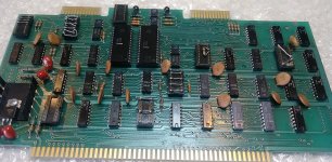
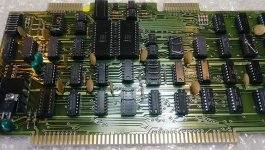
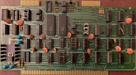
These are the two boards that I have, that I am trying to examine, to see how and possibly why they may have been configured the way that they are currently configured.
SIO-1.jpg SIO-2.jpg


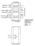
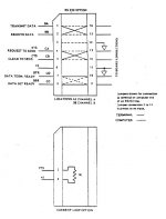
This is standard RS232 for A3 & B8
A3 - B8.jpg

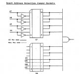
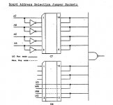
This is D6 and C7 which seem to be Port Select
D6 - C7.jpg

I found this on the schematic, and it shows B11, but I am unsure how I would setup the jumpers.
Baud Rate.jpg
 
First, these are not standard SIO cards. These are newer serial cards.
What I pointed you to is used on the original SIO cards. That information will not be useful for these cards, other than they are both serial.
These are a number of UART and USART chips possibly used. The original SIO cards were completely determined by the jumpers. These two cards are not.
These cards use 8251, USARTs, These chips require that the boot code initialize these chips. They need the mode set and the internal baud rate set by software. They won't do anything without some code to get them started. From past experience working with the H89, I found that for the 8251, it takes about 51 bytes of code to get them to a minimal operation to use them to down load code. Normally these expect a EPROM BIOS to be there as a bootstrap.
I'll provide more information to you later as I'm a little busy right now.
Dwight
 
For the 8251 look at:

http://www.bitsavers.org/components/intel/_dataBooks/1979_Intel_Peripheral_Design_Handbook.pdf

page 1-25. It is for the 8251A but that should act the same as your devices. You can check the list of things that are different in this PDF.
For the baud rate selector, B11, The 8251 has two possible baud rates for either a 16times clock or a 64times clock, when using it asynchronously ( what you'll likely be doing ).
That is why there are 2 clock input selects for two baud rates. You have to determine which you need, The address selected needs to be determined to match the software you run with it. Do note that the front panel uses I/O address 0FF.
In applications that require the use of memory mapped I/O, such as chips like 6502 or 6800, you'd change the decoding. For the 8080, it typically uses the I/O instructions that is not part of the memory map.
Only 8 bits determine the I/O address. You need to refer to the software to determine what address will be used.
For the wiring of the RS232 connections. I always have a jumper box with lights to tell me which is which. From the 25 pin connection you need to have one side driving pin 2 while the others receives on pin 2. Pin 3 is just the opposite.
There are normal configurations for DTE and DCE but is seems it is rare to see such being correct. You can uses a meter or a RS232 light box. Your jumpers for RS232 need to match with what you are using to talk with it. I usually use my laptop as a terminal since I can then download code.
The 8251 needs the ClearToSend pin pulled low. You need to tie the jumpers so that is so or nothing cam be sent from the 8251. Usually the other end controls this but not in all cases. In that case you need to tie the CTS line on the RS232 pins.
Dwight
 
I did not receive an email notification, so I just took a look at this message online.
I had a friend, send me a pic of his recently configured IMS SIO board. So, I am trying to basically understand his configurations,
compared to what I am reading in the manual.

SIO-Good.jpg

I can see and partially understand the A3 and B8 jumper settings. It appears that both the A and B Ports are setup for simple asynchronous communications.
Although I am fuzzy on pins 8-9 and 7-10 going straight across. DTR and DSR

A3 - B8.jpg

I can also see that D6 seems to be setup correctly for I/O and not memory Mapped communications. And as far as I can tell on C7, He has address line A4-A7 going through inverters. I am assuming that means
that Address A4-A7 must be low, to address the board. Not clear on this.

D6 - C7.jpg

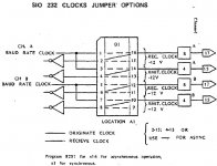
The two jumper settings that I am a little more lost on, are setting up the Clock settings on A1 and the Baud rate settings on B11. I pretty sure that I am looking for 16x and that the baud rate here is set to 9600, but I am having a hard time finding the correct documentation, showing me, that these jumper settings are set up correctly.

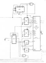
Looking at this diagram and looking at how my friend has the jumpers set, it appears that 2,4,6,8 and not going anywhere. and this diagram does not show what clock rates are actually being selected.
A1 Clock.jpg

And the only thing I have found on the baud rate settings I had to acquire from a separate schematic that I found online.

Here I might understand that the 9600 is coming from pin 1, but I am still a little bit lost, as to where it should be directed. In this case it appears that he has selected pins 11 and 12.
Baud Rate.jpg
 
If you look at the rates, you'll see that some have an A and others have a S. This is the different setting for Asychronous and Synchronous clocking rates. It is most unlikely that you'll be doing synchronous clocking but some point to point wired modems use that mode. The jumpers will have a path to each 8251's clock input and one going to the edge connector ( through a RS232 buffer ). Since you are not using synchronous you only need to connect the path going to the 8251.
Dwight
 
Before data is sent either direction the two devices need to tell each other that the receiver is ready to receive and the transmitter is sending. That's what the handshake lines do. the data then transfers on and when done the sender tells the receiver it's done. The UART needs to be setup to send data at the same rate the receiver wants to receive it or the result is garbage. Some of the setup is done in software, which is what Dwight is trying to tell you. Setting up a serial port the first time can be a PITA since the CTS and RTS pins need to be flipped somewhere so the sender's RTS line goes to the receiver's CTS. That may be the jumpers you are so worried about. Ditto with the DSR DTR pins plus the send and receive pins. This can be a problem and things like null modem adapters where used to crosswire the two devices if the board was hard wired without jumpers. The sending and receiving of data is all done in the BIOS routines of your computer and terminal and the UART needs to first know the number of start bits, stop bits and 7 or 8 bit data and again that's all send to the UART from routines in your BIOS or a program that has to be loaded into the UART.
 
Before data is sent either direction the two devices need to tell each other that the receiver is ready to receive and the transmitter is sending. That's what the handshake lines do. the data then transfers on and when done the sender tells the receiver it's done. The UART needs to be setup to send data at the same rate the receiver wants to receive it or the result is garbage. Some of the setup is done in software, which is what Dwight is trying to tell you. Setting up a serial port the first time can be a PITA since the CTS and RTS pins need to be flipped somewhere so the sender's RTS line goes to the receiver's CTS. That may be the jumpers you are so worried about. Ditto with the DSR DTR pins plus the send and receive pins. This can be a problem and things like null modem adapters where used to crosswire the two devices if the board was hard wired without jumpers. The sending and receiving of data is all done in the BIOS routines of your computer and terminal and the UART needs to first know the number of start bits, stop bits and 7 or 8 bit data and again that's all send to the UART from routines in your BIOS or a program that has to be loaded into the UART.

That is why I recommend using a RS232 light box with jumpers. Althugh, there are standards for DCE and DTE, it is rare to find anyone actually following them ( RS232 is a signal voltage and current standard only ). As for things like duplex, unless you are talking about a mechanical machine like a teletype, it is handled in software, not in jumpers.
Dwight
 
I struggled recently getting an RS232 link working between a computer and a type and talk (TNT) unit, the connections were not standard and neither a null modem nor a straight cable would work for two way communications, so I wrote some general notes about the RS232 hookup that possibly might be of some help:

RS-232 hardware flow control & DB25 connections:

The topic of RS-232 serial connections appear to have created much confusion over the
years.

Part of this confusion occurs because the Rx or RD labeled terminal on a modem
(DCE), pin 3, is a transmitting terminal or output and Tx or TD terminal on pin 2 is
input. Likewise RTS pin 4 is an input and CTS pin 5 is an output.

The reverse is true on a computer (DTE) where Tx is on pin 2 and is an output, Rx on
pin 3 and is an input, RTS on pin 4 an output and CTS on pin 5 an input.

This means the cabling for a “computer to modem link” is a straight pin for pin cable with
the labels, in order computer to modem: Rx to Rx, Tx to Tx, RTS to RTS and CTS to
CTS.

Obviously, in any RS-232 link of any kind, DTE to DCE, or DTE to DTE, or DCE to DCE,
either simple or with hand shaking, outputs are connected to inputs (of the actual line
driver and receiver IC’s) in all cases, never outputs to outputs or inputs to inputs. Simply
paying attention to this fact avoids a lot of grief.

Also to add into the mix, in the case of RS-232 links with handshaking, the RTS is used
differently for the DTE to DTC link versus the DTE to DTE link. For example, in the
connection of a computer to a modem (DTE to DCE) when there is data that the
computer wants to send to the modem, the computer asserts its RTS output which the
modem receives on its RTS input. When the modem is ready to receive, it asserts its
CTS output, which signals the computer on its CTS input, to then send the data. If the
modem de-asserts its CTS (say if its buffer is full) the data transmission stops or pauses
until CTS is reasserted. And when the computer (DTE) has finished transmitting it deasserts its RTS.

However, to throw a cat into the pigeons, if both of the connected devices are DTE (two
computers for example) the handshaking protocol is different. It requires that the RTS
and CTS of each computer are cross connected as in Computer.a to Computer.b; RTSa
to CTSb, RTSb to CTSa.

For example, in this arrangement, computer.a asserts RTSa to signal computer.b that it
is ready to receive data from computer.b. Computers.a and computer.b check their
CTS inputs to determine when it is ok to send to the other computer.
This is why two computers or two DTE‟s can be linked with a Null Modem cable which
has the Tx & Rx and RTS & CTS connections both crossed.
 
Back
Top