• Please review our updated Terms and Rules here

Broken Cromemco 8k Bytesaver

m_thompson

Veteran Member
Joined
Jul 8, 2014
Messages
1,990
Location
Rhode Island, USA
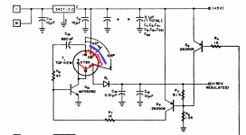
We are working on a Cromemco 8k Bytesaver in an Altair 8800 at the Rhode Island Computer Museum. Today we found that the 30V power supply was not working. Using the diode function in a DVM the voltage drop base-collector is 0.85V and base-emitter is 1.6V for Q10. The base-emitter value was much higher than we expected. We unsoldered it and tested the Hfe in using the DVM and it was only 11. We ordered a NOS replacement from eBay. Hopefully that will fix it and we can program some 2708 EPROMs with it.
 
Our power supply designer guessed at the transformer design. I will try it in LT SPICE to see if it will work, and to determine the turns ratio in the transformer.
 
We unsoldered it and tested the Hfe in using the DVM and it was only 11.

Looking at the circuit, this does not surprise me at all. Some interesting research work was done by Motorola demonstrating that if you zener the B-E junction of a transistor, it ultimately causes it to experience a drop in hfe.

I have attached a circuit showing the likely internal configuration of the transformer.

One way to analyse this particular circuit is to think of it as a single ended Royer Oscillator (a type of multivibrator) where one transistor and its associated components have been removed, shown in the attached diagram in RED ink, so ignore that, it is conceptual, however it helps to explain what happens with the transistor in your circuit during part of its operating cycle, the part where the transistor is turned on and conducting. For this part of the cycle (assume turns number N1 = N2), the transistor Q10 is biased into initial conduction by the 1k resistor (from the feedback circuit), 5v is applied across winding N1, the current in N1 starts to increase. 5V appears across N2, which adds to the 5V supply, it appears on pin 1 of the transformer as +10V. This charges the 680pF capacitor quite rapidly, and that charge current, reinforces the base current of the transistor Q10. Q10 is switched on. However, the base current starts to fall away as the 680pF capacitor charges, at a certain point there is not enough base current to keep Q10 in saturation, so its collector voltage rises. As that happens the rate of change of current in the primary winding N1 starts to fall, so the induced voltage in N2 falls further weakening the base drive to Q10. Q10 therefore rapidly comes out of conduction. Terminal 1 of the transformer has a voltage that now swings towards ground. Because the 680pF cap was near fully charged on the moment before this happened, even with pin 1 near ground, the base of the transistor will have a negative voltage.

If it was a circuit with the imaginary transistor in Red was present, then the next half cycle would just be a mirror of the first one and easy to analyse. However, without that transistor, when Q10 is cut off, the voltages you will see result from the previously stored magnetic energy in the core, that field collapsing, as the transformer rings with its own inductance and self capacitance determining the frequency and the peak voltage too. The voltage level you get on the collector of Q10, therefore when it is cut off, is a high voltage positive pulse, stepped up a little more by winding N3, which is then peak rectified to charge the filter capacitor Cf.

As Dwight noted before it is a type of flyback supply.

Also during the time that a positive going pulse is present on the collector terminal on pin 4, a similar magnitude negative pulse appears on pin 1 and will go below ground and the B-E junction reverse biased. If that is over about 7 to 10V it could zener the transistor's B-E junction. After a while the current via the 1k resistor will discharge the 680pF and ultimately turn the transistor Q10 on again damp the oscillations of the inductor and restart the cycle.

If you could measure the inductor's self resonant frequency (which takes its self capacitance into account), and its primary inductance between pin 2 & 4, and the peak voltage on pin 1, 4 and 5, it would be dead easy to make one with the correct properties and turn's ratios.
 

Attachments

  • inv.jpg
    inv.jpg
    43.2 KB · Views: 1
I'd forgotten about the back voltage zener of the transistor. You'd need a turns ratio enough to bring the output to the +33v( ?forget the voltage ).
A long time ago, I used the zener voltage of the base-emitter as a white noise generator. The voltage is typically right on the edge of avalanche breakdown. If biased at a low current it makes a noisy zener. I used it for a surf sound generator that I got a schematic for from a magazine.
Anyway, the turns ratio has to consider the current lost to the zener of the junctions rather than charging the capacitor for the high voltage out.
Dwight
 
The regulation is slightly different on this board version but it is the same transformer, XT8K. The pins look to be numbered differently but they should still be wired the same. Your schematic shows pins 2 and 3 numbers swapped ( possible schematic error in one or the other ). Using your schematic, the primary would be 2 to 3 and 3 to 4. The secondary would be 2 to 5. Otherwise it is the same transformer.
Dwight
 
Last edited:
Dwight, for my diagram I went by the pin numbering on the attached diagram.

pin 2 supply, pin 1 feedback, pin 4 collector,, and 3 & 5 the secondary. The circuit you posted on the Bytesaver II has different pin numbers, but the same transformer

It is customary in these sorts of step up supplies to make use of the voltage on the collector, so the secondary is connected there to improve the efficiency of the transformer and requires less secondary turns.

One thing I could have mentioned about this design, unlike some flyback supply designs, the transformer is not run to near magnetic saturation. By applying more base current, the transistor stays on longer for its part of the cycle, the current in the inductor is higher at the moment the transistor switches off, so the stored magnetic energy is greater and hence the magnitude of the voltage pulse on the transistor's collector and secondary is higher. So its easy to regulate the output voltage by controlling Q10's base current via the 1k resistor.

I would also "guess" for a 30V regulated supply the peak voltage should (in the unregulated maximum sate) rise to at least 50V. If the collector peaked to 25V, then its possible the winding ratios could be 1f:1c:1s (f = feedback winding pin 1 to 2, c = collector winding pin 2 to 4, s = secondary winding pin 3 & 5).In other words all winding the same turns numbers. But it could also be something like 1f:2c:3s, if the peak collector voltage was lower, it required a bigger step up and if the feedback winding had less turns than the collector winding to help reduce the chance of zenering the transistor's B-E.

If somebody had a working board it would be easy to put the scope on it to determine the ratios.
 

Attachments

  • inv2.jpg
    inv2.jpg
    61.1 KB · Views: 1
Last edited:
Also.... they fouled up more than one thing on the pin numbers on the Bytesaver II schematic. The circuit there as it stands cannot work because it will not oscillate, there is no 180 deg phase shift on the tap feeding the 680 pF cap and transistors base, so at the bare minimum they got the pins 1 & 2 mixed up.
 

Attachments

  • inv3.jpg
    inv3.jpg
    44.1 KB · Views: 1
I am trying to LT SPICE model the Royer Oscillator, but have not gotten it to resonate yet.

Using a pulse generator to control Q10 and can adjust the transformer turns ratio to get 30V output from the supply.
 
Also.... they fouled up more than one thing on the pin numbers on the Bytesaver II schematic. The circuit there as it stands cannot work because it will not oscillate, there is no 180 deg phase shift on the tap feeding the 680 pF cap and transistors base, so at the bare minimum they got the pins 1 & 2 mixed up.

The diagram shows no polarity dot of the windings. The secondary can be ignored as it isn't need for the oscillation. I'd need to think about the winding polarities a while but I believe you are right, the polarity of the windings look to be wrong between the rail and the capacitor. The older schematic shows a different regulation but that can be ignored for now.
 
I am trying to LT SPICE model the Royer Oscillator, but have not gotten it to resonate yet.

Using a pulse generator to control Q10 and can adjust the transformer turns ratio to get 30V output from the supply.

If your spice model doesn't include noise, it may never break into oscillation. You may need to give it an initial kick to start the oscillation. It needs to be enough to get the transistor into the non-linear actions. Try reversing the polarity of the small winding from the rail to the capacitor feedback.
In any case, start the simulation with an initial value other than zero.
Dwight
 
The diagram shows no polarity dot of the windings. The secondary can be ignored as it isn't need for the oscillation. I'd need to think about the winding polarities a while but I believe you are right, the polarity of the windings look to be wrong between the rail and the capacitor. The older schematic shows a different regulation but that can be ignored for now.

It would not help, the Dot markings, in this case, because it, pin 1, is drawn as a tap on the primary. This implies the polarities of the two halves of the primary without dots. For dot markings showing the winding phases, to be of any use, then the two windings would have to be drawn separately, each having two connections. So clearly this is a schematic drawing an error, where, regardless of pin numbering, the power supply connection should have been connected to the tap on the primary winding.
 
If your spice model doesn't include noise, it may never break into oscillation. You may need to give it an initial kick to start the oscillation. It needs to be enough to get the transistor into the non-linear actions. Try reversing the polarity of the small winding from the rail to the capacitor feedback.
In any case, start the simulation with an initial value other than zero.
Dwight

Yes this is a real thing with symmetrical circuits like a multivibrator as there is no initial imbalance to start it in Spice. However, in this particular circuit (which is like an asymmetrical single ended mutivibrator) it will always start if there is zero initial charge on the 680pF capacitor and zero initial inductor current.
 
I am trying to LT SPICE model the Royer Oscillator, but have not gotten it to resonate yet.

Using a pulse generator to control Q10 and can adjust the transformer turns ratio to get 30V output from the supply.


The tricky part with the Spice model is specifying the initial inductance and the winding self capacitances. I'm guessing in a small inductor like this they are unlikely over 50pF. The inductance and the capacity set the self resonant frequency and the peak voltage, along with the energy stored per cycle in the inductor, and the inductor must be large enough that it does approach saturation during the time that the transistor is turned on, we could roughly guess that from the circuit.

One way to start is to choose an operating frequency, say around about 50kHz. A half period is 10uS. Pick an initial inductor , primary inductance say 5mH, the initial current rise will be 5V/5mH =1000 A/Sec. After 10uS the inductor current would be 10mA.

The inductor stored energy per cycle would be ((0.01)^2 x 5mH)2 = 0.25 uJ.

During the inductor ringing cycle the energy is transferred to the self capacitance, so the voltage on the primary (using CV^2/2) at its peak will be about root ( 2 x 0.25E-6 / 50 pF ) or root 10000 = 100v peak (in practice it will be less due to losses).

So I'd recommend in the Spice model, initially make the primary inductance 5mH and its self capacitance in the range of 50pF to get the "model" going. You could distribute the self capacitance over the secondary as well.

If the oscillations don't start, try putting in a value of initial inductor current or some initial voltage (charge) on the 680pF cap and kick start it that way.

I could point out that some styles of circuits with inductors, can be more difficult than others to model in Spice. You could always try an experimental lash up if you don't succeed with the model. Most of the required parameters can be worked out on paper.
 
Last edited:
Back
Top