• Please review our updated Terms and Rules here

Dusting off my Processor Technology Sol-20

Mike_Z

Veteran Member
Joined
Dec 1, 2013
Messages
1,713
Location
Near Milwaukee Wisconsin
I've had a Sol-20 sitting on the back bench for many years. I purchased it from a roofing chemical company company in the early 1980's. They were upgrading to one of the 'new' Apple systems. Their complaint was that after the unit was on for about 1/2 hour, it would lose it's mind and run wild.
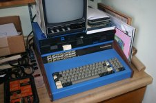
IMG_1296.jpg
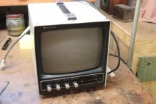
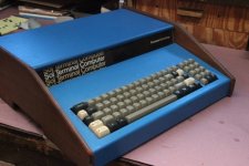
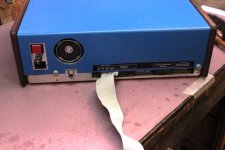
Here it is, it came with an Omega 3 hard sectored drive system, a Sanyo composite monitor and some software. It has dates on it like manufactured March 1978. Once I got it home and opened up I found that the roofing company had packed the S-100 slots full of memory boards. There were 4 boards filled with the old 2102 memory chips. Well, it didn't take long to figure out they had a heat problem. These boards would warm up the box until there was thermo run away. My first project with this unit was to build a single memory board with all the memory on it, using a 43256 and two 8464 memory chips, 48k of memory. This reduced the heat generated allot and the computer seemed to work very well. My kids learned BASIC on this machine. But then time went on and the Sol was pushed to the back bench. When I retired a dozen or so years ago, I pulled it out and found that the keyboard was not working very well. So, back to the back. Later I found an article that talked about repairing the keyboard. I copied it and promptly forgot about it again. Today, now that the weather is turning cold and outside activities are waning, I pulled the article and re read it. Seems that repairing the capacitive keyboard key is not a difficult job. I purchased a 'space blanket', but was having trouble finding the open cell foam. I thought I'd try a small hole synthetic sponge.
So, the Sol was moved to the work bench and opened up. Here is the OmegaByte drive box
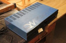
IMG_1483a.jpg
Here is the Sanyo monitor
IMG_1484a.jpg
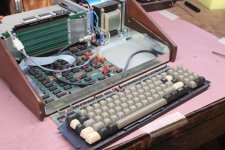
Here is the Sol-20
IMG_1485a.jpg
IMG_1486a.jpg
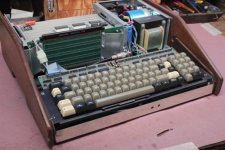
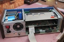
Here you can see my 'new' memory board
IMG_1487a.jpg
IMG_1488a.jpg
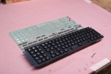
And with the keyboard out.
IMG_1489a.jpg
IMG_1491a.jpg
IMG_1492a.jpg

So, as I said I want to try and use the sponge for a spring, but am still searching for some open cell foam, Does anyone know of a source for this stuff? Thanks Mike
 
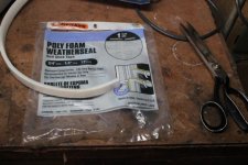
Thanks for the advise. I see that the TexElec pads are on back order, so no telling when I would get them. Since I enjoy experimenting with items, I think I'll try making my own first, just to see how different things work. I emailed TexElec and asked how long the back order is. I also have been reading many of the posts here and see that some people have had luck with weather stripping. Maybe tomorrow I can stop at the hardware store and pick up some. Mike
 
I've purchased several sets of their foam pads, with good luck in rebuilding TRS-80 keyboards. However, when I used them in my Sol 20, only a couple of keys worked. I ended up using the pads from a Sun Type 4 keyboard, which worked well. I don't know why the TexElec pads didn't work in the Sol, but you may have better luck.

The technical explanation of why some pads do not work in the SOL-20 keyboard is in this article:

http://worldphaco.com/uploads/HARDWARE_DIAGNOSTIC_TOOL_FOR_THE_SOL.pdf

The best result is to take the pads from the SUN 4 keyboard, because they result in the capacitance increase at a key press being more than adequate to be reliably detected for all keys.
 
Well, it didn't take long to figure out they had a heat problem. These boards would warm up the box until there was thermo run away.

There are serious heat dissipation issues in the Sol-20, there are a number of ways to address it.

Many were fitted with a power transformer euphemistically said to allow for brown out conditions.

In my Sol , with a line voltage of 94V rms, there is 8v delivered to the backplane (fully loaded with cards). That is suitable as the 7805 regulators on most S-100 cards requre at least 7.5V input. Also, under these conditions the input voltage to the Sol's own 5V discrete design power regulator is around 7.3 V, it has to be as low as 6.3V before ripple voltages appear in the 5V rail from that regulator.This regulator is an LDO design.

When the sol is powered from 115V the regulator's heat dissipation nearly doubles as the backplane voltage climbs to 9.5 to 10V. Also in the Sol, the cards are stacked horizontally, trapping heat between them.

1) the first move is to lower the line voltage to your sol, use a variac, = Variable rotary transformer, use a 200W unit at least though the Sol's power consumption is about 60 to 80W. (there have been other methods using a bucking transformer added in the sol, that is messy and not adjustable unlike the variac), so as to get the line voltage down, probably like my unit it will need to be around 94V rms.
When you have your S-100 cards loaded, adjust the variac to get 8V on the backplane or input to the S100 cards. At this point you would measure about 8.3 to 8.6V directly on the 56,000uF capacitor's terminals due to wiring voltage drops.

2) fit a cooling fan, see attached photo. To do this you should not modify or damage anything. It can be done simply by adding two hex screw spacers on two screws already there and use thumb nuts to secure it so that you can remove it to remove cards. Make sure it rotates in a direction that assists the direction of air flow across the cards, from the main fan, You do not need to cut any holes in the Sol's top cover for this added fan (as I have seen some people do, spoiling the housing). You need to manufacture/craft an aluminium mounting bracket for it.

The above moves will solve your heat issues.

(I'm just about to publish a design on a constant voltage machine I made for my Sol-20, probably later today, I will post it in the S-100 section).

After you read the article I referenced on the reply on the post above, you likely will conclude the smart move is to get new pads from a Sun 4 Keyboard. By the look of it, you have the type of pad carrier where these click into place with small retainers(some were glued) the Sun 4 pads have the right geometry stiff plastic base to allow this to happen and be properly retained in the carrier.
 

Attachments

  • Fan.jpg
    Fan.jpg
    175.5 KB · Views: 3
Last edited:
Hugo, some very interesting information. It will take me some time to digest it all. I read somewhere that the Mylar material has a conductive side. I have verified that on my material. The article advocated that the orientation of this conductive side is important, conductive side toward the CB. Did you notice this? I'm using a 7/16" punch to make my disks. The Mylar packaging doesn't mention the materials thickness, but I have measured approx. 0.0012". An interesting side bar here is that although I had thought that all my disk were one layer, some where actually two. The punch seems to cause some of them to attach to each other. The other item is, I'm not sure of the consistency of the thickness across the sheet of Mylar. From reading your article, the Mylar disk is the important consideration. So I figure that I'll have to check each disk prior to using it.

Yes my keyboard has the clips that grab the clear plastic disk. I only have removed a few so far. I noticed that the glue used between the disk and foam is rather stubborn to remove. A little alcohol softens it up and it comes off. The sponge I selected for the spring pad is not working out well. When I punch them out, they turn into small hamburger buns, the edges are stuck together. I want to try some weather stripping foam next.

Do you think the TexElec pads may have to thick of a Mylar pad? Maybe that is why they exhibit poor performance? Maybe the conductive side of the Mylar is not consistent?

I have no source of any SUN 4 keyboards. So I believe, I'll be attempting to amke my own pads. Thanks for the help. Let you know my progress. Mike
 
Hugo, some very interesting information. It will take me some time to digest it all. I read somewhere that the Mylar material has a conductive side. I have verified that on my material. The article advocated that the orientation of this conductive side is important, conductive side toward the CB.

If you look at the article : http://worldphaco.com/uploads/HARDWARE_DIAGNOSTIC_TOOL_FOR_THE_SOL.pdf

there is a good description of the SOL's original pads.

They were not conductive on either side, not the original ones I found in my keyboard at least. I suspect that they started out a a 0.035mm thick sheet conductive on one side, which then on that side had another 0.035mm sheet applied over it, so what they ended up with was a disc that was close to 0.07mm thick, with the conductive layer close to its center, or about 0.035mm from the surface.

A calculation on the geometry and assuming the dielectric constant was about 3 and an experiment showing that the minimum capacitance increase to reliably be detected is about 10 to 15pF agreed with the measurements on the original sol pads.

I bought a number of replacement pads from different sources, none of them had the conductive layer in the middle of the film, it was on one side and unfortunately the material being to thick to reliably raise the capacitance enough for all keys. That conductive side is not supposed to touch the pcb as the constant trauma of contact will wear it off (So don't follow that other advice about facing it toward the circuit board if that is what was said). Though if you put it around this way, it will work initially by shorting the pcb tracks together on key closure, changing the mode of operation of the keyboard to a switch type rather than a capacitance type.

The keyboard will work in a switch type of mode. Any resistance across the connection on the board, less than about 68k I think, is also detected as a key closure, even though the system was not designed for it. I tried some 10mm diameter conductive rubber discs (for calculator and remote controls etc) they worked, but I did not do this as I wanted the keyboard original and the SUN 4 type work perfectly. Also, there is no need to apply any abrasive cloth or paper to the pcb tracks where the keys are, you could clean them with IPA if you wanted, when the pads are correct (like the sun 4 type) it will work fine, or if you can replicate the original pads, but it would be a matter of finding/making the correct metalized film. I had wondered about "unwinding" a polyester or polypropylene axial capacitor to get it.


Sun4 keyboards are pretty easy to get:

https://www.ebay.com/itm/320-1018-S...42d9a35c151e4d233b7d|ampid:PL_CLK|clp:2334524
 
Last edited:
...PS: I bought a Sun 4 keyboard from that same seller, good price I thought, but in my case it cost $60 to post it here ! They are a very well made keyboard actually and I felt a little guilty taking the pads out of it and rendering it useless, but Sol-20 keyboards are much rarer, so that offsets cannibalizing it I guess. Still I can imagine in the distant future someone desperately searching for a working Sun 4 keyboard.
 
Well..... I'm going with making my own. I spent the weekend reforming the capacitors in the power supply. Seemed to work out just fine. After that I load tested the power supply and that also looked good. The +5, +12 and -12 voltages were right on the money. This morning I reconnected the power supply, the monitor and the keyboard CB sans the keys. The unit came on, no smoke was released. I glued one of my Mylar disk to my finger and pressed it on each of the key pads on the CB and the monitor recorded the correct key code for each one. So I'm rather confident that that this keyboard will work once the key pads are restored. Today, I hope to get out to the hardware store and look around for some other types of foam to make the key springs from. Mike
 
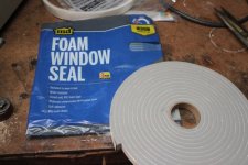
Well.... I got to the hardware store and found some small cell weather stripping. It cuts with my punch very well, so I get some nice crisp clean pads of foam. It already has adhesive on it I may try using that first. I glued a Mylar disk to the pad and stuck the pad to my finger and pressed on the CB. I tested all the keys and everyone works first touch. So I got a little anxious and tried one of the console commands, DA 0000H, 0100H. It didn't work. All the was displayed was a '?'. So I dug out the manual and tried all the console commands for displaying memory etal. They all resulted in the question mark. I tried different number formats, made sure the letters were all cap's. Nothing but '?'. Then I remembered from the dark distance past that a command EX would execute a memory address. This command was not in the manual. So I tried to go to DOS EX 2A00H, same thing. The last address I tried was zero, EX 0000H. For some reason this seemed to work, the console was rebooted. The screen cleared and the > prompt came back. So it does something. Maybe I have forgotten more than I thought. Not surprising with my advanced age. I'll have to go back to the documents I have to see where the EX command is explained. Maybe there are more primitive commands that I do not remember. Anyone know of this? Thanks Mike
 
I took some time to make a single Mylar pad, using the new weather strip material I purchased today. Then assembled it into the space bar of my keyboard. The space bar works just like new, the others are still rather poor. So maybe tomorrow, I'll go into production and see if I can bring the keyboard back to life.

I did find in the SOL documentation the console commands. EX works and so does DU(mp). My memory needs to be refreshed some. I looked at a few memory spots, but they are all filled with 00H or 0FFH. I tried EN(ter) to try and change a few addresses and this also worked. SO things are looking up, even though someone else's memory is not so good. Mike
 
I always make my own pads. I use a punch from Harbor Freight, a mylar space blanket from Walmart and clear plastic sheet from the hobby store. For the foam, Home Depot has a low density white foam. I use the adhesive on the foam to attach it to the plastic and then use contact cement for the space blanket making sure the conductive side is not touching the foam side. I lay it out in a giant 8.6" 11" sheet, then grab a block of oak underneath as a backing and start punching out discs. This works for my multiple Sol-20 systems, the Sol-20 in the VCF museum and I have done a bunch of Apple Lisa keyboards this way.

Cheers,
Corey
 
Corey, That's just about how I do it. Maybe tomorrow I can post some pictures. Today, I made 15 pads for the numeric number pad. Assembled the keyboard and tested the keys. All worked except 4 and 5. Both keys exhibited what looked bounce. The correct number would be shown and then 3 or 4 more odd characters. So I decided to try making new pads for these spots. The number 4 problem was resolved, but 5 is still troublesome. I'm a little concerned that the weather stripping I choose for the pad is too dense. So this afternoon I found some other weather stripping that may work better. We will see tomorrow. Thanks Mike
 
Corey, That's just about how I do it. Maybe tomorrow I can post some pictures. Today, I made 15 pads for the numeric number pad. Assembled the keyboard and tested the keys. All worked except 4 and 5. Both keys exhibited what looked bounce. The correct number would be shown and then 3 or 4 more odd characters. So I decided to try making new pads for these spots. The number 4 problem was resolved, but 5 is still troublesome. I'm a little concerned that the weather stripping I choose for the pad is too dense. So this afternoon I found some other weather stripping that may work better. We will see tomorrow. Thanks Mike

It is not to do with the density of the foam, though it has to be dense enough that the thin dielectric film is pressed flat onto the pcb surface. In the case where some keys work and some don't, it is indicating that the total rise in capacitance on key closure is borderline. It needs to ideally be 15pF or more to drive the key detect differentiator-amplifier enough to overcome the threshold detector. Otherwise, the output of the amplifier is just below the value of the threshold detector. It really means that the metalized dielectric film you are using, has either too thick a dielectric layer, or that the dielectric constant is too low, or both.
 
Hugo, I think you are correct. I believe the reason for the failed key operation was that I had a multiple Mylar disk on that key. Here are the two foam weather strip products I have used. The first was called a medium density foam
IMG_1495a.jpg
This foam seems to work fine but gives the key stroke a rather stiff feel. The second form was called a low density foam
IMG_1494a.jpg
This foam also works and gives a keystroke feel which is more like I remember on this keyboard. I want to test both, so I have the medium foam on the numeric pad and will use the low density on the rest of the keyboard.

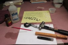
Here is my tool setup
IMG_1493a.jpg
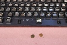
I'm using a 7/16" General brand steel hole punch, which I purchased at the hardware store. The punch will make both the Mylar and foam disks. When I make the Mylar disks, I have the Mylar folded a number of times. This makes more disk at one time, but the disk seem to stick together. I have to use a needle to pry the disks apart. Then to make sure that two or more disks are not still together I use my micrometer to check it one. I found that if two or more are used together the key doesn't work well. My key pads have a clear plastic disk that snaps into the keyboard. I use the needle to pry them out. They will have a lot of old glue and sponge residue on them. Most times my arthritic fingers can smear the glue off, but once in a while a little alcohol is needed to soften it up. I then use the alcohol to clean the disks. Once everything is ready, I apply a little contact cement to the clear plastic disk. I use the needle again to pick up only a small amount of glue and then smear it around. The foam pad is them pressed to the disk, the same is done with the Mylar disk. I then wait an hour to make sure the cement is dry, then the pad is re installed in the keyboard. Again I use the needle to make sure the plastic disk snaps into the key holder.

I only had time to make 16 more keypads. It is hard on my fingers and eyes. So maybe tomorrow I can get another 16. At that rate I should finish by the weekend, provided all the keys work. Thanks Mike
 
Just a tip when you reassemble the keyboard. Make sure when you reattach the keyboard, and fit the self threading screws into plastic, that you do this:

1) when you first insert the screw into the hole very gently rotate it initially anticlockwise, at some point it will drop down a little into the hole, which means that the metal threads on the screw are in correct alignment with the threads previously made in the plastic and then when you rotate the screw clockwise, the screw will run down the previously made threads, rather than trying to cut new ones, crossing the old threads. (this is an important technique to preserve threads in plastics that most people either don't know about or ignore in the hurry to put something back together).

2) As you rotate the screw clockwise, watch very carefully, you only want to tighten it to the point where is approximates the pcb surface to to the key assemblies, as soon as it is there, with the head engaging the pcb surface on one side and the key assembly on the other, don't tighten it more than 1/32 to 1/16 of a turn more, or just use a very light touch if you are able to feel the force increase as it tightens. This also avoids more damage to the threads in the plastic.

Plastic threads are much less forgiving than metal ones.

Plus, if you are careful, then if you have to disassemble it a few times, because some of your pads don't work, the damage to the threads will be limited.

I do admire your determination to make your own pads though.

One advantage of the known to work Sun 4 pads, is that it does not require multiple disassembly of the keyboard off the pcb more than once, which is less stress on those plastic threads.
 
I really dislike plastic. It mostly a single use product. You have to be real careful when dealing with it. As you say, it is very easy to snap off, strip or break plastic fasteners. I have done a a little work with attempting to repair striped out plastic holes. Over size drilling and gluing in a plastic plug and then drilling a new hole. This some times works, but it is better if you do not have to do so.

Making my own pads is taking some time, but I'm retired and it helps fill my day with satisfying work. Today I made another 16 pads. This time I was plagued with cement hairs and small blobs of cement that stuck to everything. I found it is important to keep my hands and tools clean. Then I dropped one of the clear plastic disks on the floor. I spent 1/2 hour looking for it. The damn thing must have rolled and was found some distance from the bench. But progress is being made. I had enough of this project for today. Now onto the next project. I'm working on a 1910 Waterbury kitchen clock. I need diversity so that I use different muscles in my hands, eyes and brain. More keyboard tomorrow. Thanks Mike
 
The damn thing must have rolled and was found some distance from the bench. Mike

It reminds me of these song lyrics:

On top of spaghetti
All covered with cheese
I lost my poor meatball
When somebody sneezed.
It rolled off the table
And onto the floor
And then my poor meatball
Rolled out of the door.
It rolled in the garden
And under a bush
And then my poor meatball
Was nothing but mush.
 
Now there is something I have not thought of in a long thime. That must be from the early 1960's. Glad that my disk did not turn into mush! Mike
 
Back
Top