NobodyIsHere
Veteran Member
- Joined
- Dec 21, 2006
- Messages
- 2,410
Hi,
I have a hand built S-100 chassis I am restoring and recently discovered that the motherboard contains active termination. However the circuit is not working. The S-100 bus motherboard still works but has a lot of noise on it and I think it would work better were the active termination circuitry still functional.
The homebrew active termination circuit is very much like the CompuPro/Godbout one mentioned on Herb's retrotechnology site.
http://retrotechnology.com/herbs_stuff/s_term.html#legacy
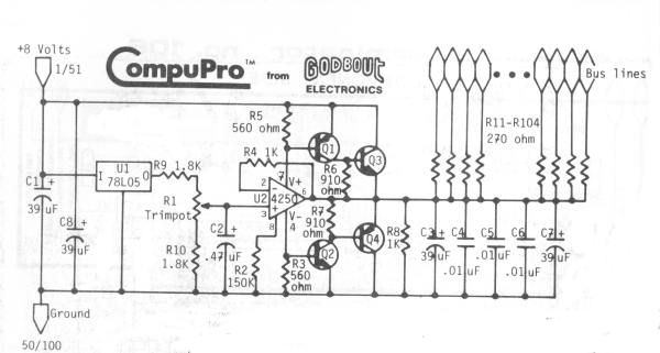
The problem is there is no voltage coming out of the circuit and into the S-100 bus lines. When I measure the voltage at the LM4250 OpAmp at pin 6, I read 0 volts relative to ground. In other words, 100% of the voltage from the +8 volt rail is being dropped across the top section of the circuit.
I believe this means the top end of the circuit is not working and there is a problem with either R5, R6, Q1, Q3, or the LM 4250 OpAmp. Now, I do not think the resistors are bad since I measured those in circuit and they seem OK. After powering on the circuit, I measured V+ at pin 3 of the LM4250 and it reads 0 volts relative to ground which seems highly suspicious. I checked the output of the 7805 and it is providing +4.90 volts at its output so I think it is OK.
Moreso, I measured the voltage across R5 and it also measures 0 volts. (!?) Looking at the circuit again, I measured the voltage across pin 1 (emitter) and pin 2 (base) of the Q1 and it also is 0 volts which is suspicious. I would expect at least a 0.6-0.7 volt drop across the emitter-base PN junction in the circuit. When I power off the circuit, I tried to detect continuity across Q1 pin 1 and pin 2 but it reads as an open circuit. When powered on though, it acts like a short.
I measured the voltage across the pin 3 (collector) and pin 1 (emitter) of Q3 and it reads the entire +8 volt rail which is something like +9.5 volts or so.
My diagnosis is Q1 is bad and needs to be replaced. However, I am not 100% sure and would like to know if anyone has any thoughts or ideas on debugging this circuit.
Thanks in advance.
Andrew Lynch
PS, thanks to Herb for posting the information on his website for the active termination circuit. It has been a huge help and Herb is a pillar of the vintage computer community.
I have a hand built S-100 chassis I am restoring and recently discovered that the motherboard contains active termination. However the circuit is not working. The S-100 bus motherboard still works but has a lot of noise on it and I think it would work better were the active termination circuitry still functional.
The homebrew active termination circuit is very much like the CompuPro/Godbout one mentioned on Herb's retrotechnology site.
http://retrotechnology.com/herbs_stuff/s_term.html#legacy
The problem is there is no voltage coming out of the circuit and into the S-100 bus lines. When I measure the voltage at the LM4250 OpAmp at pin 6, I read 0 volts relative to ground. In other words, 100% of the voltage from the +8 volt rail is being dropped across the top section of the circuit.
I believe this means the top end of the circuit is not working and there is a problem with either R5, R6, Q1, Q3, or the LM 4250 OpAmp. Now, I do not think the resistors are bad since I measured those in circuit and they seem OK. After powering on the circuit, I measured V+ at pin 3 of the LM4250 and it reads 0 volts relative to ground which seems highly suspicious. I checked the output of the 7805 and it is providing +4.90 volts at its output so I think it is OK.
Moreso, I measured the voltage across R5 and it also measures 0 volts. (!?) Looking at the circuit again, I measured the voltage across pin 1 (emitter) and pin 2 (base) of the Q1 and it also is 0 volts which is suspicious. I would expect at least a 0.6-0.7 volt drop across the emitter-base PN junction in the circuit. When I power off the circuit, I tried to detect continuity across Q1 pin 1 and pin 2 but it reads as an open circuit. When powered on though, it acts like a short.
I measured the voltage across the pin 3 (collector) and pin 1 (emitter) of Q3 and it reads the entire +8 volt rail which is something like +9.5 volts or so.
My diagnosis is Q1 is bad and needs to be replaced. However, I am not 100% sure and would like to know if anyone has any thoughts or ideas on debugging this circuit.
Thanks in advance.
Andrew Lynch
PS, thanks to Herb for posting the information on his website for the active termination circuit. It has been a huge help and Herb is a pillar of the vintage computer community.
Last edited: