• Please review our updated Terms and Rules here

TRS-80 Model I horizontal video instability

Eudimorphodon

Veteran Member
Joined
May 9, 2011
Messages
6,965
Location
Upper Triassic
Instead of doing a "jumbo" everything thread maybe it makes more sense to do problem specific ones so they might be easier to find later. So:

I have a TRS-80 Model I that has an interesting issue with the video output. Upon being initially powered up from cold it displays clear text output, but within a few seconds it starts looking a little "jumpy". This lasts for about 45 seconds with subtle worsening of the stability until suddenly it all goes to heck and the monitor comes close to losing horizontal sync. Here is a video captured through a composite cable, the symptoms apply regardless of monitor, including an original Radio Shack one.


The waving subtly changes amplitude as the machine warms up, so after 10 minutes or so it becomes "almost possible" to read the screen again (with the letters rapidly alternating between forward and backwards italics) but sync never really locks in again. The characters seem properly formed so it doesn't appear to be a major issue with the divider chain. In the tech manual "Z6" is described as the source of the horizontal sync pulse, would a partial failure of that IC cause these symptoms?
 
You could drag out your O'Scope and a can of Freeze Mist, then chase the Vertical and Horizontal Sync pulses to the combined SYNC Signal
on Pin 8 of Z5. Shouldn't take long to see what is going on. You can also use a small heat source to raise the temperature on the suspect
part. A small heat shrink gun is a good heat source.

Larry
 
After spending some time stepping through the hsync circuit description in the manual I think I have ideas where I need to clamp on the oscilloscope probes, but if someone has a second I could use a quick confirmation about the parts I should have on hand when I sit down to work on it. Just double-checking: this circuit appears to rely on both the switching speed and (possibly) the threshold voltage of the 74C04 (and maybe the 74c00?) components? I’m guessing that subbing HC or HCT isn’t going to fly here.
 
You could purchase a few parts such as:
R43 or R44 10K
R20 or R21 100K Pot
C26 C27 Vertical circuit
C20 C21 Horizontal circuit
MM74C04N and MM74C00N

and have them laying in your parts box for the next xx years, or find the culprit and just order exactly what is needed.
I typically just order what I need after chasing the signals. Don't overlook cold solder joints, as well as R43 & R44.

I don't remember what I changed on the last Model 1 I repaired.

Larry
 
Well, I've dug into the machine and no luck so far narrowing it down without shotgunning. The power supply voltages for both +12v and +5v were on the low side (4.8v for 5v) so I adjusted that, and I also replaced the big 10,000 and 2200 input capacitors just because they looked a little sketchy, but no improvement. (If anything it made things "worse" in the sense that the hsync is always wavy even from a cold power-up. Or maybe that's better because it's consistent?) The delay circuit of R20 and C20 seems to be working correctly so far as I can tell.

R43 reads around 3.5k instead of its marked 10K. If I'm understanding the manual correctly it and C21 are responsible for controlling the length of the Hsync pulse so that's certainly fishy. Tomorrow I'll drag out the oscilloscope and try using the HDRIVE pulse as a trigger to time if the HSYNC pulse is coming out wildly different lengths.

(I'm also thinking I should check HSYNC relative to VSYNC and make sure the counter chain is consistent about spacing the HDRIVE signal.)
 
... Okay, so it's official, I think: I've been completely wasting my time in the video section.

Today I kind of "shotgunned" a couple more parts based on bad assumptions. I replaced R43 with a brand new 10K resistor because it was reading around 3.5K in circuit. Much to my surprise/disappointment the new resistor *also* read about the same value. Long story short, apparently the CMOS logic chips related to the video hardware in this machine leak enough current through their gates to ground that they throw off resistance measurements, at least with my cheap VMM. In the process of figuring that out I also replaced C21, to no effect. (I wanted to try some nearby values because I thought if the resistance were actually off changing the cap to compensate might help. Yeah, stupid.) So this is where I finally got smart and dug out the oscilloscope, which I should have done in the first place.

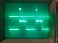
I hooked up one probe of the scope to the HDRV input on Z6 and the other probe on the output that goes to the sync mixer, Z5. I had noticed that the video was most stable when R20 was adjusted so the text appeared in the middle of the screen, and it got trashier the closer you got it to the normal margin or beyond. Here's what it looks like when there's almost zero delay between HDRV and the pulse: (Note that this isn't directly on HDRV, for these shots I'd moved the trigger after the first couple stages of inverts in Z6; the tops of the CMOS peaks are sharper square waves than the TTL input.)

sharp_pulse.jpg
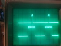
It's difficult to see in the photo but the length of the pulse is consistent and the edges reasonably clean, and here's what it looks like with a delay:
blurrier-pulse.jpg
Again, difficult to see, but as you move R20 the pulse ever more wildly fluctuates in position.

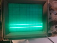
The elephant in the room here is WTH is going on with the peaks of these pulses. After wasting some time working along the chain I decided to take a look at just the 5v feed. Here's the baselines with the scope set for 1v per division and the power off:
flatline.jpg
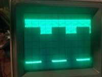
And here's what I get with the power on. Trigger is on the lower line and is still the CMOS-ed HDRV:
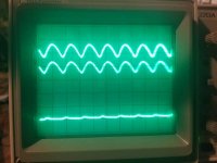
hashpower.jpg

In other words there's about a voltage worth's of "hum" in the 5v line that my voltmeter wasn't seeing. I checked the 12v line and it's clean, it's just the 5v line that's having this problem. Aaaagh!

Would someone be able to educate me a bit on how the TRS-80 Power supply works? I guess I probably need to start by reading the datasheet for the 723 regulator, but analog circuitry is not my strong point. A frustrating thing is I did replace the 10,000uf input capacitor because I was worried the one there was "sketchy", and after the replacement the problem stopped being a "warm up" issue and became constant. After discovering this situation I tried doubling up the old cap with the replacement:

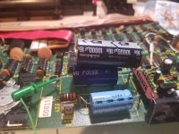
doublecaps.jpg
And for a *brief* few moments I ended up with a stable screen, but after turning the machine off to replace my probes it was back to behaving just like it had been.

If I probe the + side of the 10,000uf cap the amount of "flutter" looks almost as much as I'm getting on the 5v line. I do not have an ESR meter, is it possible I just had the bad luck of getting *two* bad new capacitors (I tried both of the replacements I purchased) and the old one is also intermittently bad, or is it just coincidence that I briefly saw a sharp screen after screwing with the input capacitor and this flutter should be filtered out further in? The only other "large" capacitor I see in the 5v section C10, a 10uf radial, and I kind of have trouble believing it should be filtering out this much trash? The thing that bothers me is it looks to me like the frequency of this trash is a lot higher than 60hz.

Any help would be massively appreciated.
 
The only other "large" capacitor I see in the 5v section C10, a 10uf radial, and I kind of have trouble believing it should be filtering out this much trash? The thing that bothers me is it looks to me like the frequency of this trash is a lot higher than 60hz.

I realized right after posting that the frequency of this is something I can and should check. Here's what it looks like with the SEC/DIV knob set at 2 microseconds. (I don't know if I entirely trust the time calibration of this scope but it's probably correct within an order of magnitude.) Nice pretty sinewave between about 4 and 5v riding on top, and it is not present on the 12v line at all. I checked again on the input side of the 10,000uf cap and I think it might be just a ghost bleeding through the ground or something. What could be causing this?

Click image for larger version  Name:	2microsecond_trace.jpg Views:	0 Size:	72.6 KB ID:	1225647

EDIT: I calibrated the scope timebase to the expected hsync pulse frequency and based on that the frequency of this hash appears to be about 10 microseconds peak to peak.
 
Last edited:
… the manual mentions a “frequency compensation capacitor” between pin 13 and 4 on the 723 to prevent “the op-amp loop from going into oscillation”. Would “oscillation” in this circuit look like the waveform/variation I’m seeing?
 
Hello Eudimorphodon,

sorry to hear you are having problems with your Model I TRS80. You seem to have it narrowed down to the Horizontal
Sync circuit or maybe the 723 internal power regulators. I took my model 1 apart and checked Z6 Pin#13 and Z5 Pin#8
and got similar results to what you have posted so I don't think the sync circuit is totally borked. Have you
inspected the variable resistors R20 & R21 as they get noisy with age. I replaced mine with multi-turn resistors.
Have you checked for solder cracks on the Pins of Z5 and Z6? Look at Q2 with a scope to see if that may be a
problem, may be simpler to just replace it (2N3906). Have you checked for solder cracks around the 5P video
connector. As to the 723 voltage regulators, you mentioned the +5V has noise while the +12V does not. If you don't
have a replacement 470pF capacitor, you could swap C12 and C13 to see if the noise problem moves to the other 723. I
don't get any noise on my +5V line or supplies but I have a low end Rigol Scope so maybe I just don't see it. DC
coupled shows no noise and AC coupled shows nothing (measuring DC voltage). I would be happy to check out other
parts of my machine if it would help.

>>> Charles

:attachment Scope BMP file
 

Attachments

  • NewFile0.zip
    3.3 KB · Views: 3
I don't get any noise on my +5V line or supplies but I have a low end Rigol Scope so maybe I just don't see it. DC
coupled shows no noise and AC coupled shows nothing (measuring DC voltage).

I'm sure you'd see it on any modern scope better than I do on my ancient Tektronics; it's really hard to miss. I really am kicking myself for faffing around for several hours before deciding the scope was the only way to go, found it in ten minutes.

(I showed the trace to a HAM radio friend of mine and his first question was why in the world the high level readings were so fat.)

I'm going to try replacing both the frequency regulator cap and the output can (the 10uf one) as soon as I can work on the machine; I had to pack the whole mess up to clear up my desk for "real job" so I probably won't get back to it until the weekend. No brain I've tried picking yet has been able to tell me if it's likely to be as simple as one of the capacitors or if this is more likely the 723 regulator itself or a problem with the big op-amp it's actually regulating. (It's the obvious candidate for something that warms up.)
 
You can tell a lot about the 723 by verifying the voltages at all the pins on the 723. There is a very good write up in the Model 1 Hardware Manual.

Larry
 
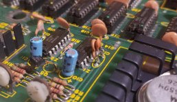
The issue was indeed voltage regulation. Checking out the 723 the zener reference voltage was clean, as was the 5v input reference, so I figured the issue was either the frequency compensation capacitor, the output filter caps (although I was skeptical of that theory, the sawtooth looked too nasty for that), the op-amp, or the regulator itself. To cut to the chase tacking a new capacitor across the legs of C12, the frequency compensation cap:

piggyback_cap.jpg - Click image for larger version  Name:	piggyback_cap.jpg Views:	0 Size:	109.2 KB ID:	1226686

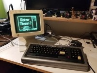
Nailed the problem. (I probably should desolder the old one, but my desoldering skills are... weak, and I hate threatening old boards with them unless I absolutely have to.) Video is clean and the machine is working well enough now to do this:

meteor_mission2.jpg - Click image for larger version  Name:	meteor_mission2.jpg Views:	0 Size:	122.4 KB ID:	1226687

It's kind of amazing that this thing was working at all with such a nasty sawtooth on the +5v supply. Oldskool TTL electronics can be surprisingly resilient.

Edit: FWIW, I made a video that's mostly me waving around schematics, pointing at things, and spouting nonsense, but if you're new to oscilloscope-ing maybe there's something to be said about walking through the process of probing one place and as a result getting tipped off about a problem somewhere else.
 
I'm super impressed that you went through all this debugging. Personally, the capacitors on there are decades past their life span. I would consider them to ALL be bad and necessary to replace. I usually do that for any system before turning the power on. I mostly collect mini-computers though. But again, impressive debugging.
 
Back
Top