• Please review our updated Terms and Rules here

Risers for Model III

Tibs

Veteran Member
Joined
Dec 10, 2016
Messages
847
I had posted that I wanted some of these in the Items wanted forum, however I got to thinking....which is always dangerous. So I'm about to upgrade a Model III cassette to disk and have a power supply, drives, two controllers and don't think they come with them. Haven't opened it up yet, work has been busy this week.

Has anyone ever fabricated them? I don't have a brake to bend sheet metal but racking my brain trying to figure out how to get my hands on an ideal material that is easy to work. I've seen some plastic ones in my time and not sure if there is a shielding best practice with going that route? I don't want something that is unsafe (heat/fire) or looks horrible (Plexiglass comes to mind).
 
I have a diskless model 3 I fixed up a month ago, it does not have the mounting frame, controller or PSU - depending on where you're based I have sheet metal facilities but would need a drawing. - Im sure someone could template one for you.

I decided not to put floppies in mine and have ordered FreHD PCB's and nearly have all the parts to build them up.
 
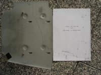
Some years ago someone on the usenet had the same question about a Model 4. I then took photos and the noted the dimensions. So below are the photos from the riser mount in my Model 4 from 2006 which found luckily on my archive harddisk today.

This riser mount is from sheet metal but I think you can use plastic material like hard PVC or ABS as well. Some installed (after-market?) Model III & 4 riser mounts are in fact from plastic material. So I think this should be no problem.

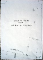
The drawings for the left & right side of the disk riser mount. All dimensions are in Millimeters.

At first side by side to original mount:
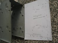
trs80floppyrack01.jpg.trs80floppyrack02.jpg

The drawings alone in a better resolution:
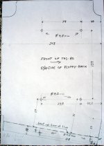
trs80floppyrack03.jpg.trs80floppyrack04.jpg

The original part is from 1mm sheetmetal. It's one piece for the two sidewalls plus the cover plate.
I don't think you really need the cover. The only need is for stability. But the stability is also given by the mounted disk drives in between. So I think you only have to fabricate the two sides. If the stability is still insufficient you can fabricate the cover as an extra part attached on top of both sides.
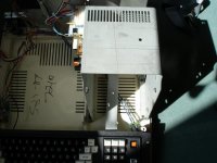
trs80floppyrack05.jpg

The two sides are different in height. The mounting holes for the drives are different (measured from the baseplate) due to the pedestal on the right side.
The rear end of the left sidewall didn't fit on the paper for drawing. I think that doesn't matter. The interesting dimensions are on the front side.
The backward tilt of the disk riser mount is 10°. All holes are 4.5mm diameter.

The two rear brackets seem to have no real purpose:
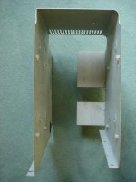
trs80floppyrack06.jpg

The left side bottom holes have slots to slide fit in the screws. I think the slots are not necessary if there are two separated sidewalls:
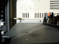
trs80floppyrack07.jpg

There is only one mounting hole per drive on the left side because the power supply unit is in the way:
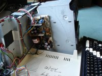
trs80floppyrack08.jpg

The pits around the drive mounting holes are about 1.5mm deep. They prevent permanent contact with the sidewalls during slide-in of the drives. Washers of this thickness glued on the inner side of the holes will answer this purpose.

The bracket on the right rear side of the riser is for the shielding of the keyboard cable and ground connection from/to the mainboard rack which is already electrically grounded. This bracket adds some stability to the mount but I think a simple wire connection for grounding could be sufficient.
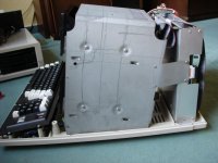
trs80floppyrack09.jpg

I hope this will help to build your own.

-Rainer
 
Last edited:
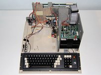
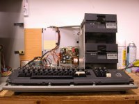
Here a two examples of riser mounts which I found on the internet. Both are I think after-market.

This is a plastic three sides cage (very sturdy):
trs80floppyrack_plastic.jpg

And this one is from sheet metal with a diagonal bracket which connects the riser and the mainboard rack for stability:
trs80floppyrack_3rd_party.jpg

-Rainer
 
The top pic (the Model 4) are the original plastic sturdy ones I am talking about. It's not uncommon to find a grey set (Model III) in an early Model 4 because RS would have had thousands of sets during the change over from Model III to 4 production.

The lower pic (the Model III) is an aftermarket set.

I've told people for years, don't be cheap, use the original risers so the disk drives line up properly in the bays.

Ian.
 
I have a few options it seems.

Pull the one out of my 4 and take to a metal shop and see how much for them to make one identical. The drawings above would help with that too and I like the idea of the power supply on the side anyway.

Buy one from Ian.

It's a clean rig otherwise and it's just to finish my collection.

My first III back in the day had the VRData kit. I think it was metal too.
 
UGH now I've discovered the CRT was cracked on the back....So need a cage and a CRT.

What CRTs are compatible for me to troll the surplus places? I've got everything else I need except the drive riser and a CRT to make this how I want it. Great case, tested MB, Controller, RS232, Drives, keyboard....Power Supply. Just no darn tube and riser.

I'll keep an eye out around here too locally but shipping those things all it takes is one Fedex person to drop it on the side or even let it sit on the side and its going to break off. Shipping these things makes me nervous as heck.

Edit, I'm going to give one of those VDC a shot and see if it works out.
 
Last edited:
For the CRT you can use one out of a Amstrad / Schneider GT65 monitor.
I have replaced my Model III white tube with a green one out of a GT65 (tube p/n: ORION 310GNB31):
http://www.cpcwiki.eu/index.php/GT64/GT65

This GT65 CRT fits perfectly. They do have the same dimensions and mounting holes as the original one. With some luck you can get it really cheap on Ebay or elsewhere. I don't know though if these monitors were sold every country.

Replacing the tube on the Model III isn't a complicated thing to to but the usual safety measures for high voltage work do apply!

-Rainer
 
So....I ordered the CRT while not so um....clear of mind :) ...and its the wrong CRT part - and was eBay - my fault.

I meant to get the one Ian has (VDC1208DP31BE) and I got the VDC1204DP31BE by getting my copy paste mixed up....It will mechanically fit, I haven't counted the pins to see if it has the same plug and all, but realistically speaking what are the chances its going to work?

I know a few threads in here have had some "fun" experiments including a guy just up the road from me in Nashville with the proper one above who gave up because it was too bright.

I've looked through the SAMS books for the Model 4 and 1. Seems the Model 4 has a few different tubes and some of the resistors are a little different based on which tube. I'm sure if its just a mater of increasing one or a few I can handle it, I'm more worried with damaging it.

So....I'm kind of torn on what to do with this $30 CRT vs getting the right one. I like a challenge so I'm not afraid to take it up. Would be kind of fun.
 
For the drive bays, perhaps cannibalize a old PC for it 5.25 bays and build a base the fits in the case. Probably not the easiest option, but it might work.. or watch for a dead model 3 somebody is selling cheap for parts...
 
I thought about the broken Model III route, but after seeing the shipping jobs of some people its just not worth the risk and I'd hate to damage one just to gut it out.

I already had an order in with Ian and the extra charge wasn't more than shipping on a Model III inside the US anyway, so I picked up his rails which makes me feel a ton better about keeping it real.

The CRT (new) is 7 pin and the end thing fits on just right, so maybe tomorrow when my elbow is usable again I'll test out the Model III with a model 4 lid.

That way I can be sure its all working before throwing the new CRT at it. I have a spare video board and yoke equipment, two spare motherboards, several spare power supplies just don't want to blow stuff up just for "troubleshooting".

I still have a Model 4P with a video board/crt issue that I haven't gotten around to yet, and may test its board out on the III as well. I really don't like messing with my Model 4 or my working 4P, those are sentimental.

Oh yeah, noticed this Model III doesn't have a shield on the back, really surprised about that. Doesn't have screw holes either, I didn't know they were allowed to ship them out like that due to the FCC rules. Its a really low serial number.
 
Back
Top