• Please review our updated Terms and Rules here

Model 1 expansion interface and floppy drive not working

Dokken

Experienced Member
Joined
Feb 27, 2018
Messages
249
Location
TN
I received the floppy drive cable from some Australian guy via ebay. excellent service on that.

i have a known working level 2 16k CPU, CPU->EI buffer cable, two expansion interfaces of unknown status (the cassette relays do click upon power up), and a few floppy drives.

I have it all connected, floppy drive on the first connector nearest EI, power up EI, floppy, CPU. not recognizing EI....simply boots to memory size, level 2 basic.

when I power the EI, I hear a loud click in the drive, like a relay.

Any pointers on where to start diagnosing? From Mav's video, I should see a garbage screen upon successful boot with the EI prior to loading dos.
 
Dokken,
Sounds to me like a typical response. Try this.
Turn on the Monitor and then Depress the BREAK Key on the Model 1 and keep it depressed. Turn Power on the Model 1.
When you see characters on the display, release the Break key and hit ENTER a couple of times.
Then type in the following:
?MEM
and depress the ENTER key. It should respond 16xxx. If that worked then Power off The Model 1.

Then Power on the Floppy Drive(s), then the EI, then Depress BREAK Key and Power on the Model 1.
When you again see characters on the display, release the BREAK key and depress the ENTER key a couple of times
then type in the following:
? MEM
It should respond with 48082 or something close.

If that worked insert Floppy in Floppy Drive, close door and depress reset button on Model 1. The EI will turn on the Floppy
Motor and try to boot the floppy. (You should be able to hear the Floppy Head being stepped as it resets.) It should come up
to the OS. ie TRSDOS, NEWDOS, or whatever you booted.

The reset Button is under the lid where the EI Cable to Keyboard Cable is located. (Opposite end of Model 1 from
the Monitor Plug, Audio Plug, and Power Plug.)

Each time you quickly depress the Reset it should boot.

Power down, by removing floppy from drive, turn off Model 1, EI, Floppy, then Multi Outlet Plug so Power Bricks are
not energized all the time. (Power up in Reverse Order.)

One other thing you need to be aware of. For the Model 1, the Floppy Drive that is at the end of the cable (father away)
from the Model 1, needs to be the ONLY floppy with the Terminator. For a ONE drive system the Terminator will be on
Drive 0. All other Floppy's need the Terminator Resistor DIP removed. The cable is a straight through conductor cable.

(All the EI Relay Click really does is lets you know it has Power and the Relay Energized, which is a good sign.
The ?MEM will tell you the current Memory that the CPU found internal to Model 1 and EI. The Floppy Drive CLICK
on Power Up is something that is NORMAL, but causes your Boot Floppy's to get glitched if you leave the Floppy
in the Drive with the Door Closed. DO NOT make this common MISTAKE as it will kill your Boot Floppy. )


Larry
 
Last edited:
Jay,
Yes the OEM Cable for the Model 1 did have missing pins for Drive Select. But, that isn't necessary because
you ONLY select one Drive per one Connector on the Cable. And the first connector after the EI Connector is
for Drive 0, next is Drive 1, and Drive 2. There are some problems associated with using Drive 3. The Terminator
Resistor is ONLY used in the last drive on the Cable.

My Model 1 has a cable with all the Pins present, and I use a DIP switch to replace the Punch Out DIP Header
that is present on the Original Floppy Drives. That makes it easy to change selections for Drives.

Larry
 
I'm talking about the interconnect cable between the EI and the M1. I'm wondering if it needs to be a buffered cable or not, and the condition of the interconnect cable. If it uses a buffered cable it could be that one or more of the LS244s has died allowing no comms between the M1 and the EI, resulting in no garbage screen.

It seems like the computer doesn't "see" the EI. First thing I would do is sub a known good M1 and see if it does the same, secondly try a different EI to confirm nothing in the M1 is causing a problem.

It's times like these it would be good to have one of Rpsi92's EI boards but unfortunately he only has the early ones left on eBay... the good ones are all sold out as best I can tell.

Cheers,

Ian.
 
thank you so much for the replies. and to Ian for the ultra-fast service on the cable from half way around the world.

I won't have time to work on this until closer to the weekend, but in the meantime i ordered an EI-CPU cable from ebay (non-buffered) and it should be here Friday.

Current interconnect cable is a buffered one with the chips. I feel like Ian is right that the CPU is NOT recognizing the EI.

This weekend I'll try the new cable. then i'll try another CPU, EI. Fortunately I've been hoarding model 1 stuff over the past year so I have multiples of everything except cables.

So excited to get this thing working.
 
Before trying the unbuffered cable, you must open the EI case and see if it has a 5V wire added to the card edge connector. If it does, using an unbuffered cable will fry the CPU.
 
Before trying the unbuffered cable, you must open the EI case and see if it has a 5V wire added to the card edge connector. If it does, using an unbuffered cable will fry the CPU.

Wow, didn't see that in the user guide. great info.
 
It won't be in the user guide. The buffered cable and din cable were modifications to improve stability of the CPU-EI system. Here's an old thread with some info

http://www.vcfed.org/forum/showthread.php?39645-Identifying-a-Model-I-Expansion-Interface

thank you. I have some reading to do. not as straightforward as I initially thought. When I was a kid and we got the EI/drives, all i remember is plugging it in and playing Zork.

From that old thread (most photos dead):
Yep, the orange cable runs 5V to power the buffered cable, running it straight to the TRS-80 is a bad idea indeed.

Does this mean that in order to use the buffer cable you need the modification with 5V to the buffer? I definitely don't have that.
 
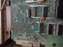
If the buffer mod was added to the EI, there will be a pin with a 5V line on the copper side of the board, and the RAS, CAS, and MUX lines to the connector are cut. The 5V is needed to drive the chips in the buffered cable.

It should be easy to see if the mods are present. I sent you and Ian the Tandy bulletin on the original modification.
 
@Dokken, if you have the wire as in the first photo, do not use a straight-through connection cable between the CPU and EI

Thanks so much. i'm 99.9999% sure no such wire in installed on either, but this photo helps and i'll double check when i get back into this.

is the inverse true that in order to use the buffer cable, this wire/mode MUST be installed?
 
Thanks so much. i'm 99.9999% sure no such wire in installed on either, but this photo helps and i'll double check when i get back into this.

is the inverse true that in order to use the buffer cable, this wire/mode MUST be installed?

The short answer is yes. The buffered cable needs +5VDC to power the chips in the black box. But wait! There's more

I just went back through this thread, and there's another important question. If you look at the photo I posted in #16, above, the RAM chips are in two rows running along the narrow dimension of the board, i.e., front to back. Tandy released a second EI which eliminated the need for the buffered cable. In the newer design, the RAM chips are in two rows along the long axis, i.e., right to left. The second design does not need the buffered cable, the DIN twisted pair modification, and won't have a wire as shown in my first photo.

The question is: Which EI board do you have?
 
Tandy released a second EI which eliminated the need for the buffered cable. In the newer design, the RAM chips are in two rows along the long axis, i.e., right to left. The second design does not need the buffered cable, the DIN twisted pair modification, and won't have a wire as shown in my first photo.

The question is: Which EI board do you have?

thanks, i just looked and both of my EIs have the ram chips oriented side to side/left to right.
 
Back
Top