mrthreeplates
Experienced Member
- Joined
- Jul 22, 2018
- Messages
- 77
Hi,
While in lockdown, I've been working on an improved version of my floppy drive switch. I'm happy to report that it is working...
TL;DR: I can boot from an external floppy on my model 4P GA, with the boot drive switchable via s/w.
Sorry for the long post, skip to the bottom if you want to see some pictures.
For my previous attempts, see my thread here.
The purpose of this switch is to allow me to boot from (and use) my external floppy drives as though they were placed internally. This is a convenient way to use a floppy drive emulator or a real floppy (interchangeably) without having to retrofit the case or swap cables each time.
My previous board, while it worked okay, had a few issues that I wanted to address:
1) On a Model 4 GA (or a Model 4P non-GA), my board requires some minor external modifications to the motherboard. I wanted to minimize these changes.
2) The floppy map was limited to one (switchable) hard wired remapping. I want to be able to select different mappings via software on the TRS-80 (perhaps via a key sequence at boot). Credit to Gonk23 for this suggestion!
3) If I fixed #2, then I wouldn't actually need a physical switch anymore (although I've kept the switch as a backup option).
4) The Model 4P only supports 2 internal floppy drives. I want to add external drives, just like my Model 4 and 3. Although there is a mod for this in the January 1986 80 Micro magazine, I wanted to reduce the number of hacking and external wires needed to implement it (while adding my floppy switch at the same time).
Additionally, I had a few extra design goals in mind:
1) I wanted to move components to the underside of the board (in case I needed it to fit in a low profile space). I was worried (perhaps unnecessarily) that my board might run into the graphics card or case on my model 4P.
2) I needed to switch to surface mount components (due to #1).
3) I needed to have the board assembled for me (due to #2).
4) I added a proper h/w debounce for the enable switch.
5) I needed to add colorful blinking leds. Okay, I really didn't need this, but they are cool.
This is also an excuse for me to do more hardware hacking.
Note that this board is only useful for TRS-80s with built in floppy drives and which share a common floppy controller design. So far this includes the M3, M4, M4 GA, M4P and M4P GA. I haven't tested a M4 or M4P (non-GA) yet.
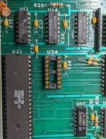
The common element for all of these floppy disk controllers (whether on an external controller or integrated onto the motherboard) is a 6-bit flip flop (using a 74LS174) that is used to latch the four drive select lines (and two additional control lines). My board replaces the flip flop with programmable logic. Minimally, this requires removing the chip and installing a socket.
As it is "illegal" (and not very useful) to select more than one drive at a time, I thought I could exploit this. Since I am using a MCU, I can monitor the drive select lines for this illegal condition, effectively using this as a code to get the MCU to change the mapping.
Additionally, the MCU I selected has the ability to emulate logic functions without the aid of software. This allows me to nearly match the speed of the original flip-flop, making the MCU act like a GAL/SPLD, but much more flexible.
So, my idea is to use drive selects 0 & 1 (simultaneously enabled) as a "flag" to tell the MCU that it should change mapping modes. This left me 4 remaining bits to play with.
In theory, the floppy drives could be re-ordered in 24 different drive combinations (requiring 5 bits). IMO, many of these combinations aren't useful, so I narrowed the list down to the 8 that I put into a table in the MCU. With 8 mappings, I only needed 3-bits. This left me with 1 free bit left. I use this bit (if set) to tell the MCU to save the current mapping in EEPROM (to be restored when the MCU first powers up). This allowed me to set the mapping either temporarily or permanently. Setting the mapping temporarily works even if the TRS-80 is reset (but not power cycled).
The way to switch the mapping (or save it permanently), is with a single out command (e.g. from BASIC).
While there are 8-bits that can be set in the out command, only bits 0, 1, 2, 3, 4 and 7 actually go to the flip-flop my board replaces. In particular, bits 0 and 1 represent drive select 0 and 1. I use bit 7 as the flag to save the mapping to EEPROM. This left bits 2, 3 and 4 for the mapping.
So, putting this all together, I can change or reset the mapping via a single command:
out 244, 3 + 4*map
or, to save the mapping permanently, I add 128:
out 244, 3 + 4*map + 128
The table of mappings I programmed is:
map 0: 0 1 2 3 (no change)
map 1: 1 0 2 3 (i.e. swap drives 0 and 1 only, drive 1 becomes the boot drive).
map 2: 2 0 1 3
map 3: 3 0 1 2
map 4: 0 2 1 3
map 5: 1 2 0 3
map 6: 2 3 0 1
map 7: 3 2 0 1
Since the MIII and M4's all have built in BASIC roms, this means I can change the drive mapping at any time. I figured I could still get myself into trouble on a M4P (since it has no basic rom) if I accidentally selected an un-bootable configuration. Because of this, and because I like switches, I've kept the enable switch.
Note: being able to s/w select the boot drive means that I can also do this via the keyboard at boot if I want. All that is required is a boot rom change (to issue the out instructions desired based on key presses). Maybe I'll try to implement this later.
So, what happens to the drives when multiple drives are selected? This is supposed to be an illegal condition! Good question. Since I would only do this when there is no i/o active, nothing should happen. As a precaution, I also have the MCU clear the drive select lines nearly immediately (< 1 microsecond), just in case. The motor does run briefly, but I don't see any drive lights come on.
Yes, all of this is a total hack. In my defense, I'm just having fun and wanted to see if I could do it. So far, it seems to work... If this breaks something, I can always reprogram the MCU.
Ok, now let me get back to the problem of those extra (4) bodge wires needed for my M4 GA (see my other thread). To solve this problem, I added an additional output on the MCU to create an "external bus" select line. This means that I only have to jumper one wire from my remapper board to the M4 GA. This can be done with a clip, just like the one used on the graphics card. Unfortunately, I still need to cut one trace. As far as I know, this is no way to avoid this.
And finally there is my M4P GA. Like the M4 GA, there are several wires and mods needed if you want to add support for drives 2 and 3 (see the 80 micro article). I moved some of this logic into the MCU. The result is that my M4P GA shouldn't need any bodge wires to remap the floppy drives *and* add support for the extra external drives. I did need to create a new floppy drive cable however (but this is fairly easy).
The M4P non-GA is slightly more complicated as it has a different floppy disk controller chip. Similar to the M4 GA, I think I'll need to cut one trace and run a jumper in it's place. As I don't have a M4P non-GA, this is only based on my analysis of the schematics... I am also not sure about the physical placement of the remapper board on the non-GA (or variants if there are different revisions). Again, I don't have one so I can't test this.
Finally, no project is complete without colorful blinking lights.
There is a green "enable" LED which lights up when the enable line is not grounded.
There is a green "default" LED which lights up whenever the current mapping matches what is saved as default in the EEPROM.
There are four row (and one bank) red LEDs showing which mapping is currently active.
There are also two modes, selected by an input pin. Non-M4P mode is the default. M4P mode is enabled by grounding the input pin.
While in M4P mode, the MCU changes how it how it "drives" drive 2 and 3, as well as the behavior of the external bus output. These eliminates some of the bodge wires which would otherwise be needed.
To visually distinguish which mode is enabled, I change the flashing behavior of the row led.
In non-M4P mode, the row LED will flash slowly. In M4P mode, the row LED will do a fast double flash. Flashing the leds also tells me the MCU is alive.
BTW: I had a really good experience with PCBWay. They built my design with very little hassle (especially considering Covid-19). At $80 for 5 boards fully built (including sourcing the parts), I can't complain at all!
There are still a few things that I'd like to fix:
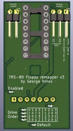
1) I messed up on the silkscreen. In particular, I added the "M4P" mode after I sent the files for manufacturing. The comments next to the pins don't match the behavior I described above.
2) I should have added through hole jumpers for Drive selects #2 and #3. This would make it simpler to use clips that would go to the floppy drive header on my M4P GA. My workaround was to add two wires directly on my M4P GA instead.
3) While PCBWay was excellent, I didn't expect that they would hand solder my boards(!). This resulted in some of the LEDs being flaky. In the future, I'll either use larger component packages or insist on machine soldering.
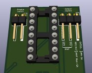
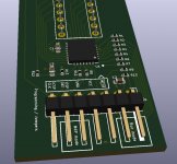
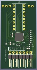
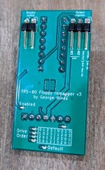
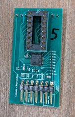
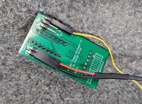
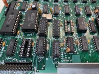
Here is a picture of the new board:
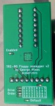
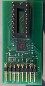
I program it with a PicKit4 (so it can be powered and it run self-tests). The programming header is also used for i/o pins for selecting the mode, the enable switch, external bus select, and as a run jumper.
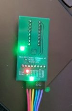
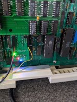
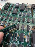
Here it is installed in my M4 GA:
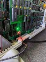
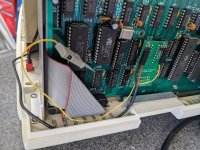
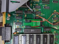
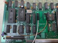
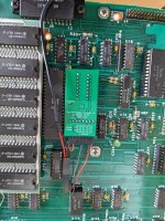
And in my M4P GA:
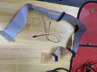
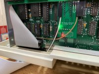
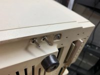
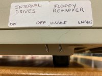
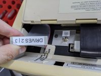
And the back of the M4P GA (with the dangling external cable and enable switch):
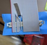
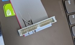
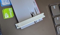
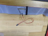
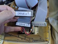
Here is the cable I had to make for the M4P GA:

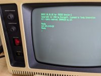
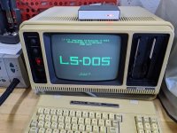
Using the out command to change the boot drive to boot from drive #2 on my M4P GA (using a HXC USB floppy simulator as the boot drive):
George
While in lockdown, I've been working on an improved version of my floppy drive switch. I'm happy to report that it is working...
TL;DR: I can boot from an external floppy on my model 4P GA, with the boot drive switchable via s/w.
Sorry for the long post, skip to the bottom if you want to see some pictures.
For my previous attempts, see my thread here.
The purpose of this switch is to allow me to boot from (and use) my external floppy drives as though they were placed internally. This is a convenient way to use a floppy drive emulator or a real floppy (interchangeably) without having to retrofit the case or swap cables each time.
My previous board, while it worked okay, had a few issues that I wanted to address:
1) On a Model 4 GA (or a Model 4P non-GA), my board requires some minor external modifications to the motherboard. I wanted to minimize these changes.
2) The floppy map was limited to one (switchable) hard wired remapping. I want to be able to select different mappings via software on the TRS-80 (perhaps via a key sequence at boot). Credit to Gonk23 for this suggestion!
3) If I fixed #2, then I wouldn't actually need a physical switch anymore (although I've kept the switch as a backup option).
4) The Model 4P only supports 2 internal floppy drives. I want to add external drives, just like my Model 4 and 3. Although there is a mod for this in the January 1986 80 Micro magazine, I wanted to reduce the number of hacking and external wires needed to implement it (while adding my floppy switch at the same time).
Additionally, I had a few extra design goals in mind:
1) I wanted to move components to the underside of the board (in case I needed it to fit in a low profile space). I was worried (perhaps unnecessarily) that my board might run into the graphics card or case on my model 4P.
2) I needed to switch to surface mount components (due to #1).
3) I needed to have the board assembled for me (due to #2).
4) I added a proper h/w debounce for the enable switch.
5) I needed to add colorful blinking leds. Okay, I really didn't need this, but they are cool.
This is also an excuse for me to do more hardware hacking.
Note that this board is only useful for TRS-80s with built in floppy drives and which share a common floppy controller design. So far this includes the M3, M4, M4 GA, M4P and M4P GA. I haven't tested a M4 or M4P (non-GA) yet.
The common element for all of these floppy disk controllers (whether on an external controller or integrated onto the motherboard) is a 6-bit flip flop (using a 74LS174) that is used to latch the four drive select lines (and two additional control lines). My board replaces the flip flop with programmable logic. Minimally, this requires removing the chip and installing a socket.
As it is "illegal" (and not very useful) to select more than one drive at a time, I thought I could exploit this. Since I am using a MCU, I can monitor the drive select lines for this illegal condition, effectively using this as a code to get the MCU to change the mapping.
Additionally, the MCU I selected has the ability to emulate logic functions without the aid of software. This allows me to nearly match the speed of the original flip-flop, making the MCU act like a GAL/SPLD, but much more flexible.
So, my idea is to use drive selects 0 & 1 (simultaneously enabled) as a "flag" to tell the MCU that it should change mapping modes. This left me 4 remaining bits to play with.
In theory, the floppy drives could be re-ordered in 24 different drive combinations (requiring 5 bits). IMO, many of these combinations aren't useful, so I narrowed the list down to the 8 that I put into a table in the MCU. With 8 mappings, I only needed 3-bits. This left me with 1 free bit left. I use this bit (if set) to tell the MCU to save the current mapping in EEPROM (to be restored when the MCU first powers up). This allowed me to set the mapping either temporarily or permanently. Setting the mapping temporarily works even if the TRS-80 is reset (but not power cycled).
The way to switch the mapping (or save it permanently), is with a single out command (e.g. from BASIC).
While there are 8-bits that can be set in the out command, only bits 0, 1, 2, 3, 4 and 7 actually go to the flip-flop my board replaces. In particular, bits 0 and 1 represent drive select 0 and 1. I use bit 7 as the flag to save the mapping to EEPROM. This left bits 2, 3 and 4 for the mapping.
So, putting this all together, I can change or reset the mapping via a single command:
out 244, 3 + 4*map
or, to save the mapping permanently, I add 128:
out 244, 3 + 4*map + 128
The table of mappings I programmed is:
map 0: 0 1 2 3 (no change)
map 1: 1 0 2 3 (i.e. swap drives 0 and 1 only, drive 1 becomes the boot drive).
map 2: 2 0 1 3
map 3: 3 0 1 2
map 4: 0 2 1 3
map 5: 1 2 0 3
map 6: 2 3 0 1
map 7: 3 2 0 1
Since the MIII and M4's all have built in BASIC roms, this means I can change the drive mapping at any time. I figured I could still get myself into trouble on a M4P (since it has no basic rom) if I accidentally selected an un-bootable configuration. Because of this, and because I like switches, I've kept the enable switch.
Note: being able to s/w select the boot drive means that I can also do this via the keyboard at boot if I want. All that is required is a boot rom change (to issue the out instructions desired based on key presses). Maybe I'll try to implement this later.
So, what happens to the drives when multiple drives are selected? This is supposed to be an illegal condition! Good question. Since I would only do this when there is no i/o active, nothing should happen. As a precaution, I also have the MCU clear the drive select lines nearly immediately (< 1 microsecond), just in case. The motor does run briefly, but I don't see any drive lights come on.
Yes, all of this is a total hack. In my defense, I'm just having fun and wanted to see if I could do it. So far, it seems to work... If this breaks something, I can always reprogram the MCU.
Ok, now let me get back to the problem of those extra (4) bodge wires needed for my M4 GA (see my other thread). To solve this problem, I added an additional output on the MCU to create an "external bus" select line. This means that I only have to jumper one wire from my remapper board to the M4 GA. This can be done with a clip, just like the one used on the graphics card. Unfortunately, I still need to cut one trace. As far as I know, this is no way to avoid this.
And finally there is my M4P GA. Like the M4 GA, there are several wires and mods needed if you want to add support for drives 2 and 3 (see the 80 micro article). I moved some of this logic into the MCU. The result is that my M4P GA shouldn't need any bodge wires to remap the floppy drives *and* add support for the extra external drives. I did need to create a new floppy drive cable however (but this is fairly easy).
The M4P non-GA is slightly more complicated as it has a different floppy disk controller chip. Similar to the M4 GA, I think I'll need to cut one trace and run a jumper in it's place. As I don't have a M4P non-GA, this is only based on my analysis of the schematics... I am also not sure about the physical placement of the remapper board on the non-GA (or variants if there are different revisions). Again, I don't have one so I can't test this.
Finally, no project is complete without colorful blinking lights.
There is a green "enable" LED which lights up when the enable line is not grounded.
There is a green "default" LED which lights up whenever the current mapping matches what is saved as default in the EEPROM.
There are four row (and one bank) red LEDs showing which mapping is currently active.
There are also two modes, selected by an input pin. Non-M4P mode is the default. M4P mode is enabled by grounding the input pin.
While in M4P mode, the MCU changes how it how it "drives" drive 2 and 3, as well as the behavior of the external bus output. These eliminates some of the bodge wires which would otherwise be needed.
To visually distinguish which mode is enabled, I change the flashing behavior of the row led.
In non-M4P mode, the row LED will flash slowly. In M4P mode, the row LED will do a fast double flash. Flashing the leds also tells me the MCU is alive.
BTW: I had a really good experience with PCBWay. They built my design with very little hassle (especially considering Covid-19). At $80 for 5 boards fully built (including sourcing the parts), I can't complain at all!
There are still a few things that I'd like to fix:
1) I messed up on the silkscreen. In particular, I added the "M4P" mode after I sent the files for manufacturing. The comments next to the pins don't match the behavior I described above.
2) I should have added through hole jumpers for Drive selects #2 and #3. This would make it simpler to use clips that would go to the floppy drive header on my M4P GA. My workaround was to add two wires directly on my M4P GA instead.
3) While PCBWay was excellent, I didn't expect that they would hand solder my boards(!). This resulted in some of the LEDs being flaky. In the future, I'll either use larger component packages or insist on machine soldering.
Here is a picture of the new board:


I program it with a PicKit4 (so it can be powered and it run self-tests). The programming header is also used for i/o pins for selecting the mode, the enable switch, external bus select, and as a run jumper.

Here it is installed in my M4 GA:

And in my M4P GA:


And the back of the M4P GA (with the dangling external cable and enable switch):

Here is the cable I had to make for the M4P GA:


Using the out command to change the boot drive to boot from drive #2 on my M4P GA (using a HXC USB floppy simulator as the boot drive):


George
Last edited:

